
After making a plant light system in a couple of IKEA bookshelves, I also designed some individual lamps to utilize smaller spaces such as window sills for plant cultivation. PCB design documents (KiCAD), manufacturing files (Gerber) and 3D models (.step) for these lamps are shared on Github, and descriptions are posted below.
LED strips
Having positive experience with GW QSLMS2.HM, a series of highly efficient horticulture LEDs from Osram, I decided to continue using these LEDs. Production will soon end for the exact types I used, but newer versions (drop-in replacements) will soon be available from Osram.
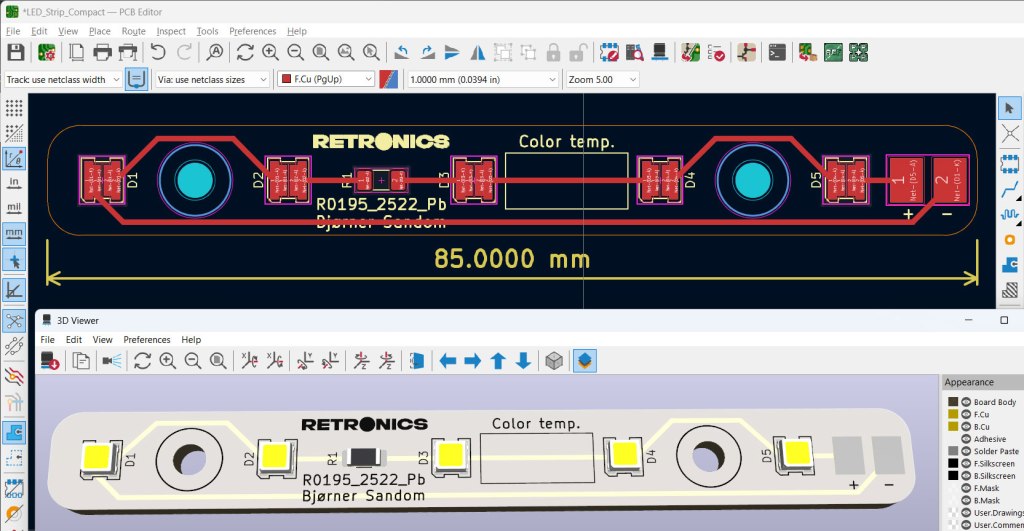
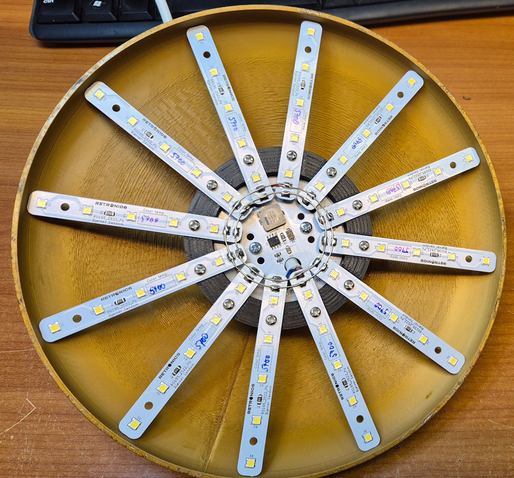
It takes a lot of these small LEDs to create sufficient light for growing plants and vegetables indoors. Though being energy efficient, they do need a way to dissipate heat, and using aluminium PCBs works well for that purpose. I designed LED strips with 5 LEDs each.
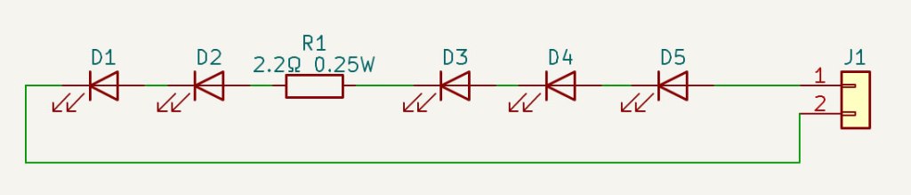
The 2.2Ω resistors help leveling out differences in current for individual LED strips due to deviations in LED forward voltage.
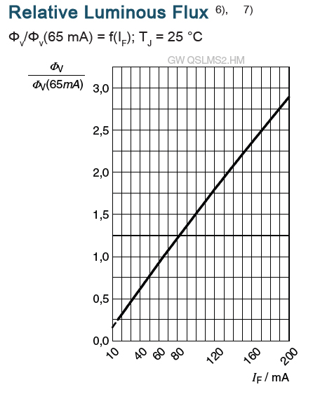
The LED datasheet indicates a luminous flux of 41 lm at 65 mA forward current, and a photon flux of 0.55µmol/s . We don’t want to drive the LEDs at their rated max current of 200mA, but 150 mA is expected to be fine. The datasheet doesn’t explicitly mention photon flux for different currents, but this graph shows that the luminous flux increases almost linearly with current, so I assume that this also applies to photon flux. If we estimate 1 µmol/s per LED when driven at 150 mA, 60 LEDs should provide 60 µmol/s.
If a lamp is placed at a distance at which it lights up an area of 0.1 m2, this area will be subject to a PPFD of 600 µmol/s/m2, which should be sufficient for light-demanding plants like tomatoes or chili.
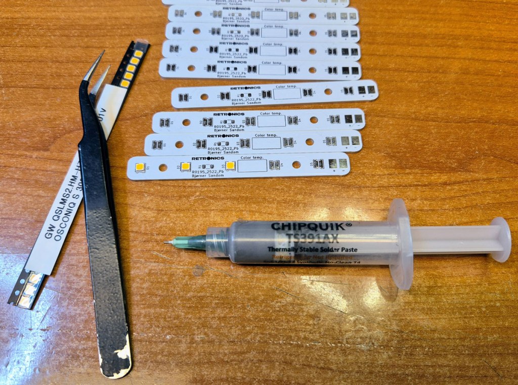
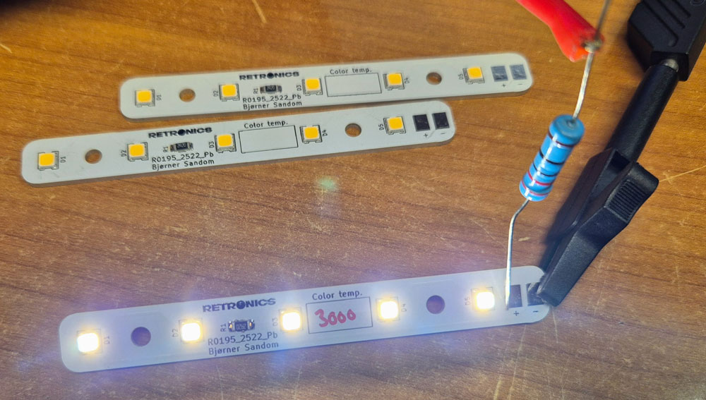
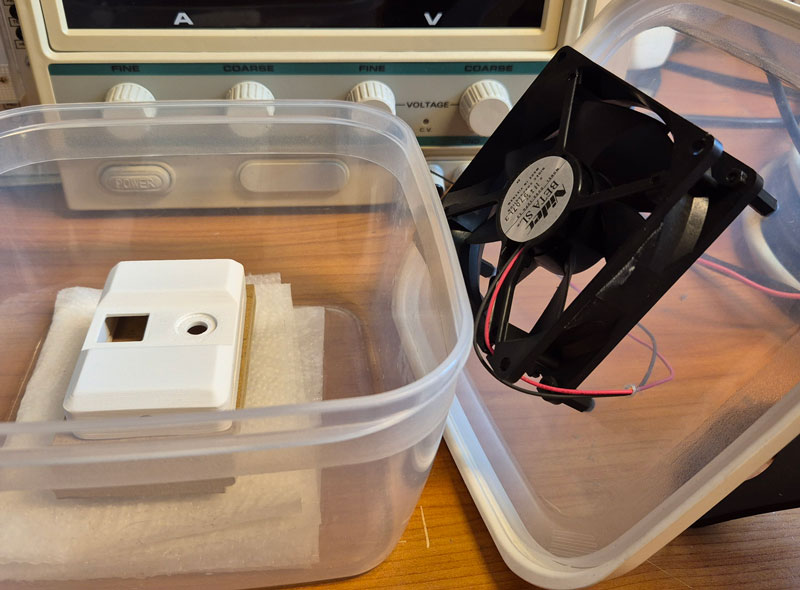
It’s a good idea to test each LED strip before assembly, e.g. by using a lab PSU and a dropping resistor. Here, I used an 18V source and a 220Ω resistor.
The chosen LEDs are available in a range of color temperatures from 2200K (warm white/yellowish) to 6500K (cold white/blueish). Different color temperatures are ideal for different plants and phases in a plant’s life. For the seedling stage of tomato plants, 5000-6500K may be optimal. In the vegetative stage, a slightly warmer 4000-5500K is better. During flowering and fruit setting, the plants will appreciate a warm white 2500-3500K. A compromise for all the stages, e.g. 4000K will probably do just fine. I made lamps with 5700K for growth and 3000K for fruit setting. The warm white 3000K is more pleasant to look at than 5700K; something to consider if you’re planning to keep the plants and lights in a living room.
LED drivers/dimmers
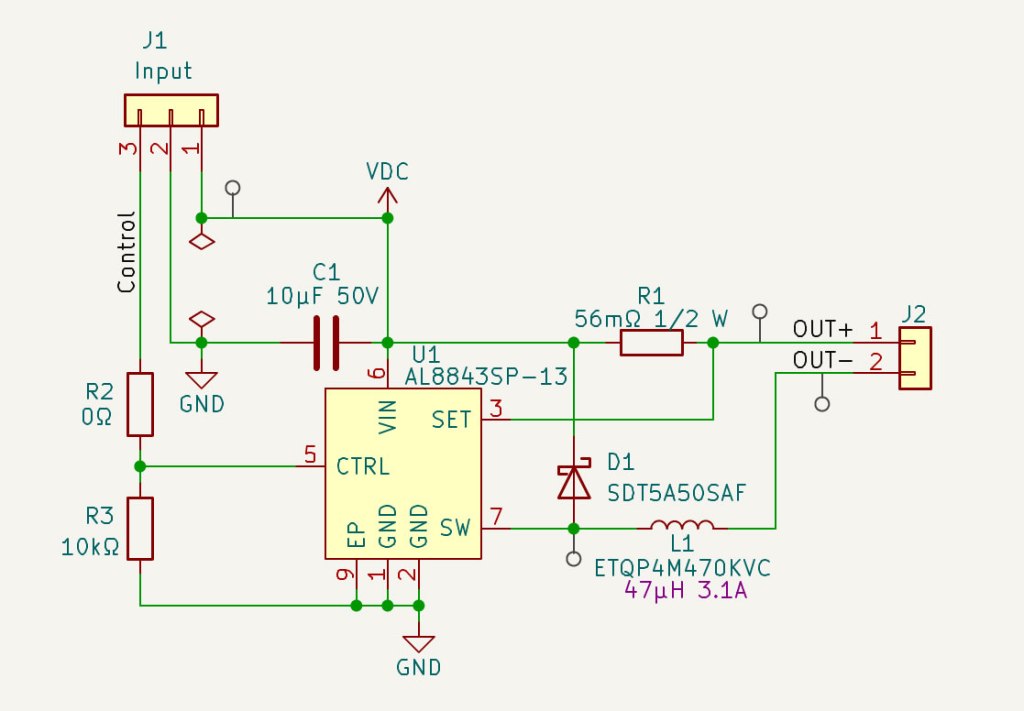
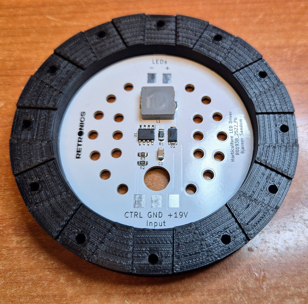
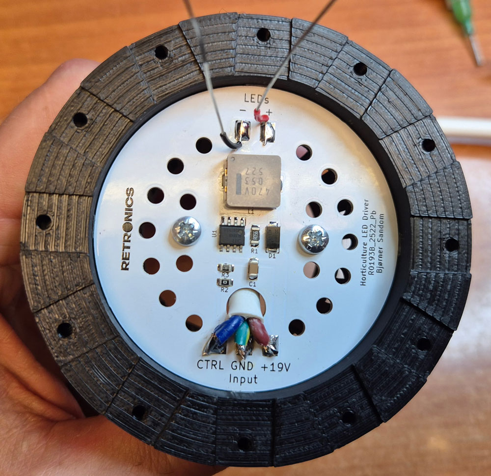
The LEDs need a stable current source to operate flawlessly, and we also want the light intensity to be adjustable to accommodate the needs of different plant types. For this project, I designed drivers/dimmers based on the AL8843SP-13 from Diodes Inc. This IC supports dimming control from either an analog voltage, e.g. a potentiometer for brightness adjustment, or PWM pulses from a microcontroller.
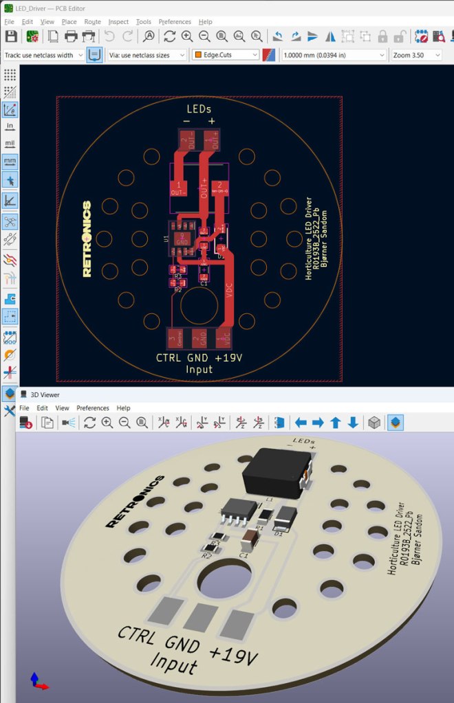
PCB design in KiCad.
Though being fairly efficient, the AL8843 and inductor L1 will need a means of cooling to keep the temperature within a safe range. Placing the components on an aluminium PCB with 60mm diameter will keep them from overheating.
The circuit is designed to be driven from an old laptop PSU, which typically delivers 19-20VDC and currents up to 3-3.5A.
If you’ve got a 24VDC PSU that you want to use for this purpose, it is expected to work just fine; the components will just be a little bit warmer.

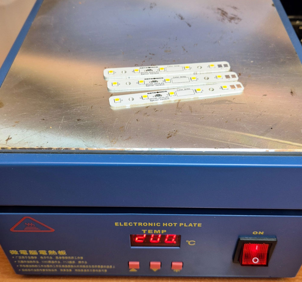
Soldering a couple of LED driver boards on a hot plate.
Lamp assembly
I’ve designed the lamp to fit on the print bed of a Prusa MK4S. Lamp shade diameter is just below 210mm. You will need a 3D printer that can print at least 210x210mm in x- and y-axis.

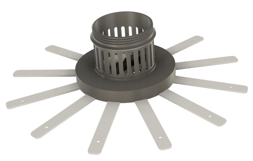
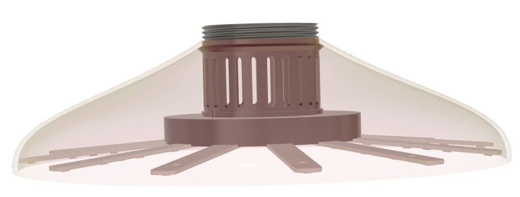
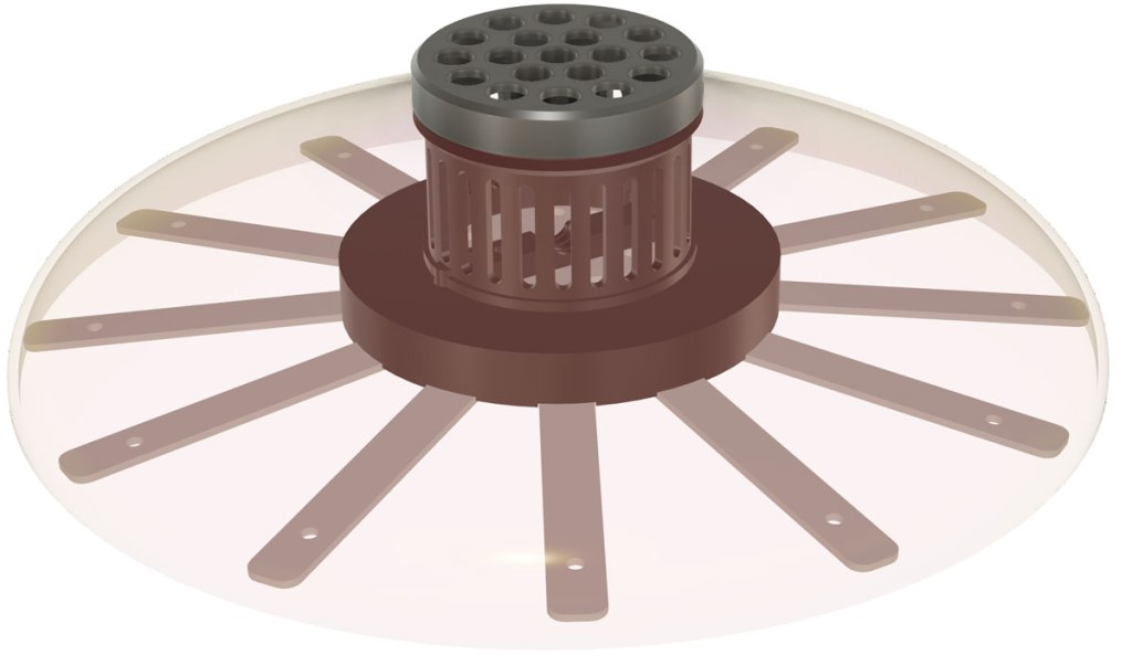
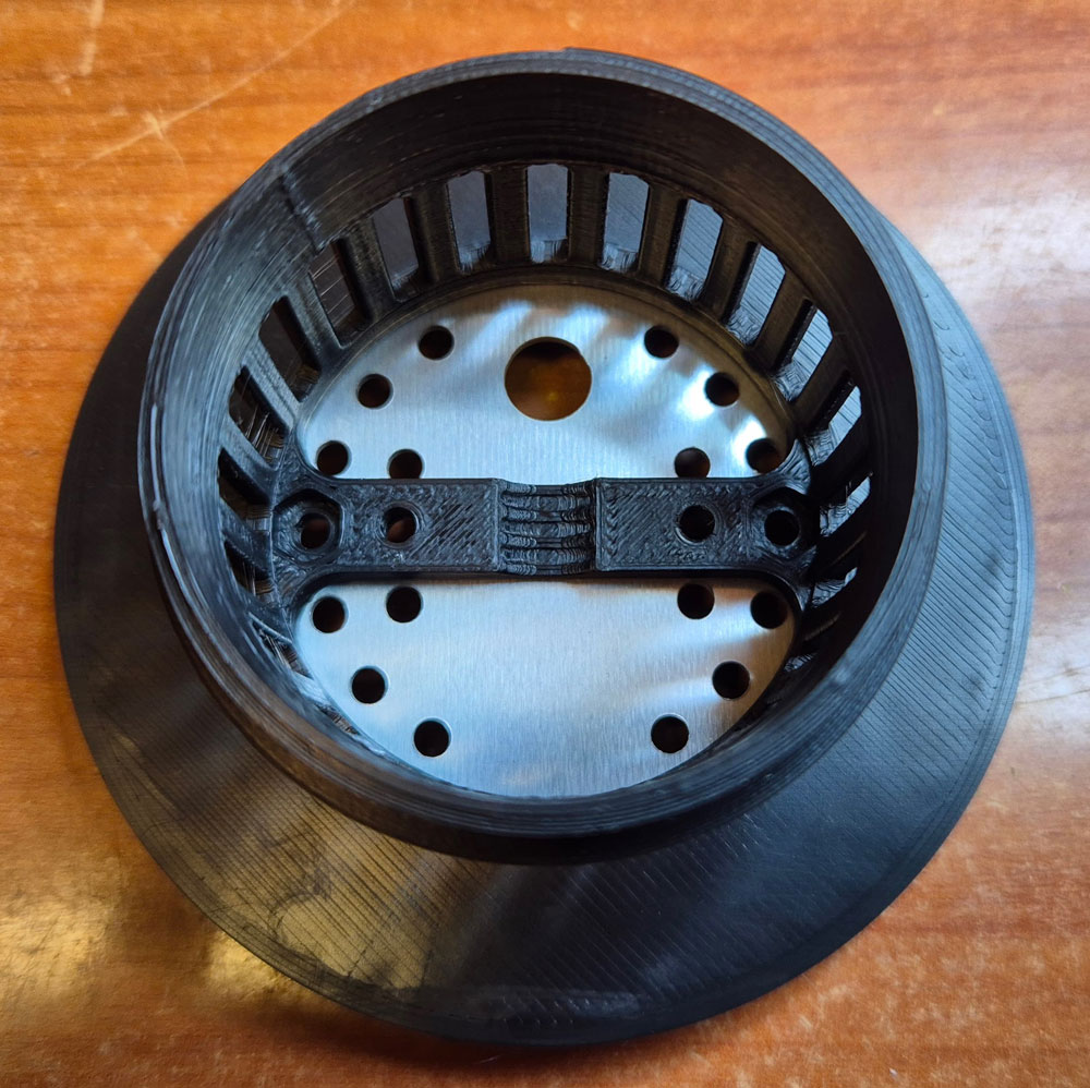
Modeling in Fusion. LED strips and driver board will be mounted on the dark grey piece in the screenshot above (LED_Strip_Holder.stl). I used ASA filament for this piece, because it can handle more than 90°C without deforming. The LED strips are mounted at a 5 degree angle, to focus the light over one plant.
Next piece is the lamp shade (LampShade.stl), which can be printed with PLA or whatever plastic material you like. I used PLA in a golden color, which is sadly discontinued. Please start making this again, Prusa.
A threaded cap (TopLid.stl) secures the lamp shade to the rest of the assembly.
Turn up the volume and listen to the happy sounds of the Prusa when printing the lamp shade 🙂


The driver PCB snaps into place in the LED strip holder.
The assembly piece is pressed on from the other side.

Strain relief is mounted with M3 screws and hex nuts. Don’t tighten these yet. Optionally, you may populate the two remaining screw holes through PCB and assembly piece, with another set of M3 screws and nuts.
Insert a 3×0.75mm2 cable through the PCB hole and the strain relief on the other side. Then, tighten the screws and solder the wires to the PCB input terminals. Cable length: as long as you need the lamp cable to be.
On the LEDs output terminals, solder hook-up wires, stripped of most of the insulation, except around 10mm at the ends facing the PCB. Wire length: around 20 cm.
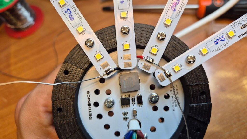

Attach the lamp shade. The ends of the LED strips shall now lean against the inside of the lamp shade.
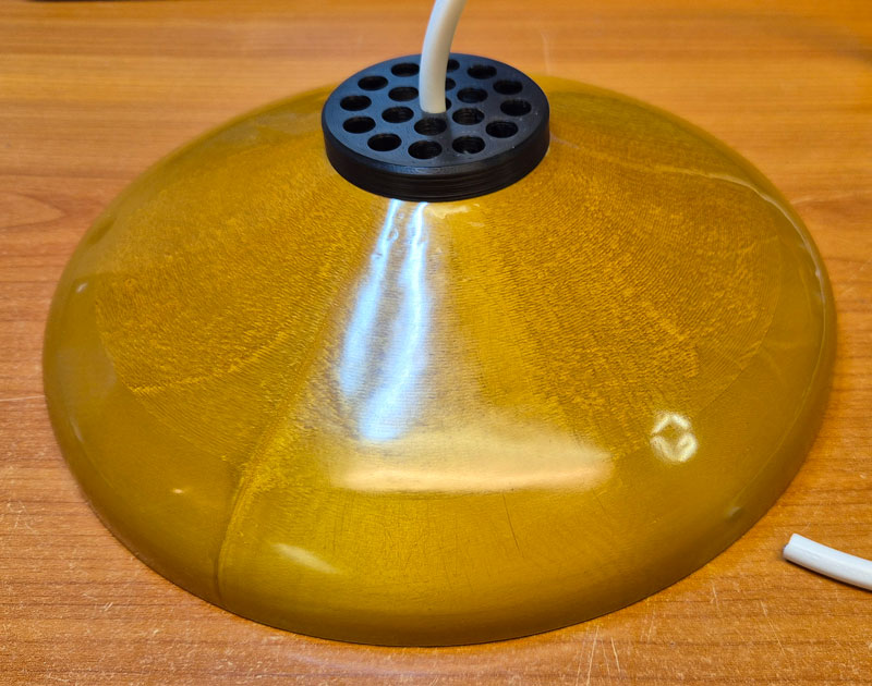
Thread the wire through the top lid, and then screw the lid on.
Timer/light controller with temperature and humidity sensors.
Your plants will need the light to be turned on and off at certain intervals, to simulate day and night. The LED drivers need a control signal (voltage or PWM) for brightness adjustment. These are tasks for a microcontroller, and an STM32F103CBT was chosen for the job.

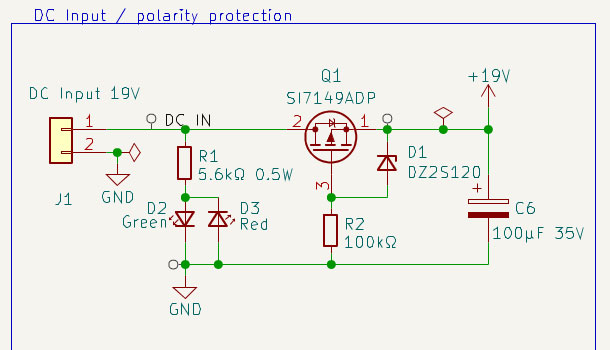
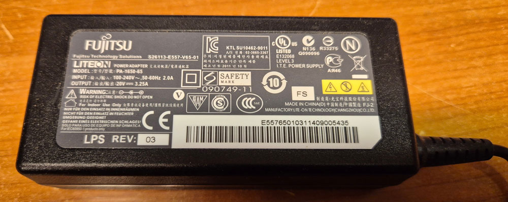
The system receives its power from an old laptop PSU, like the one shown below, rated at 20VDC/3.25A. On the DC input, there is a polarity protection circuit. If you confuse plus and minus-wires from the PSU, a red LED will shine, and nothing bad happens.
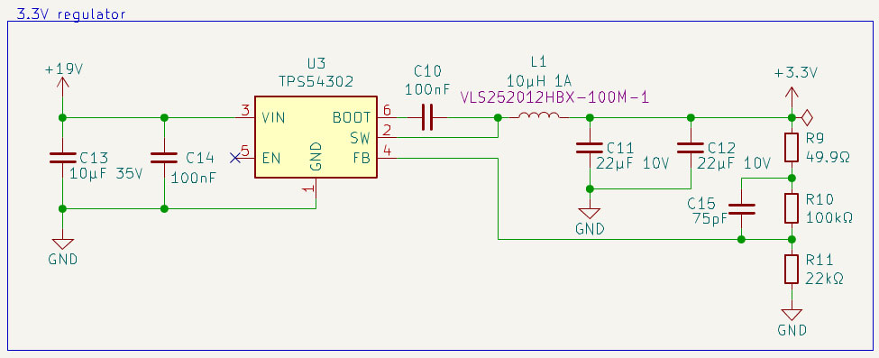
A TPS54302 buck converter efficiently steps the voltage down to 3.3V for the MCU and peripherals.
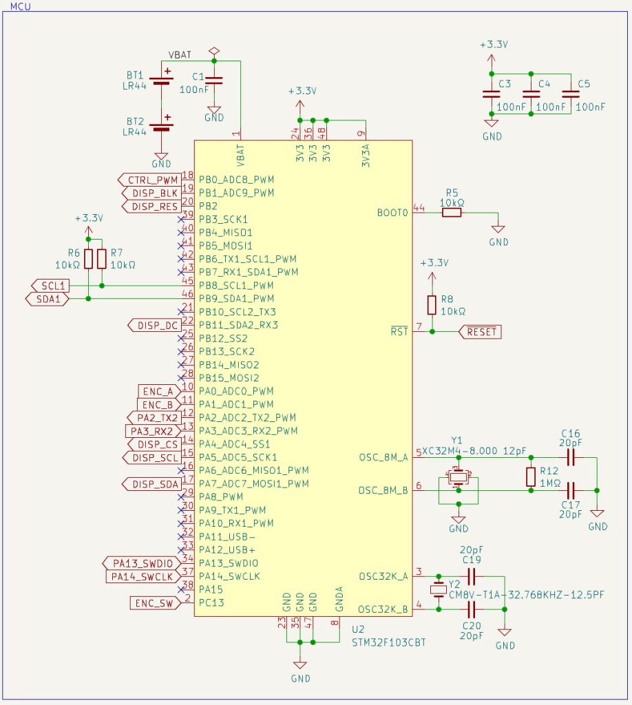
The STM32 microcontroller is surrounded by standard circuitry like decoupling capacitors and crystal oscillators for MCU clock and real-time clock. A couple of LR44 batteries keep the RTC ticking during power outages.
An SHT40 sensor provides temperature and humidity data via I2C.

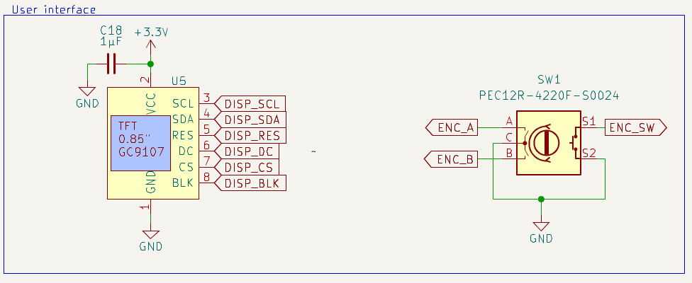
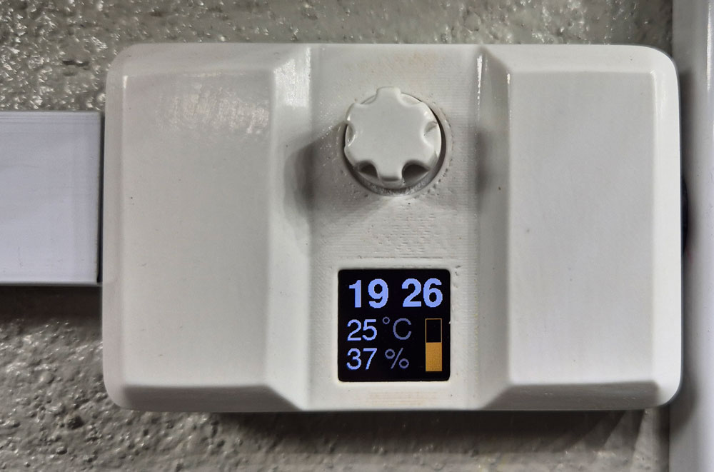
The user interface consists of a tiny TFT Display from buydisplay.com and a rotary encoder with button switch.
Burn-in may be an issue with some display types, but I’ve kept a couple of these displaying the same data for several months now, without any sign of burn-in, so these seem to be good.
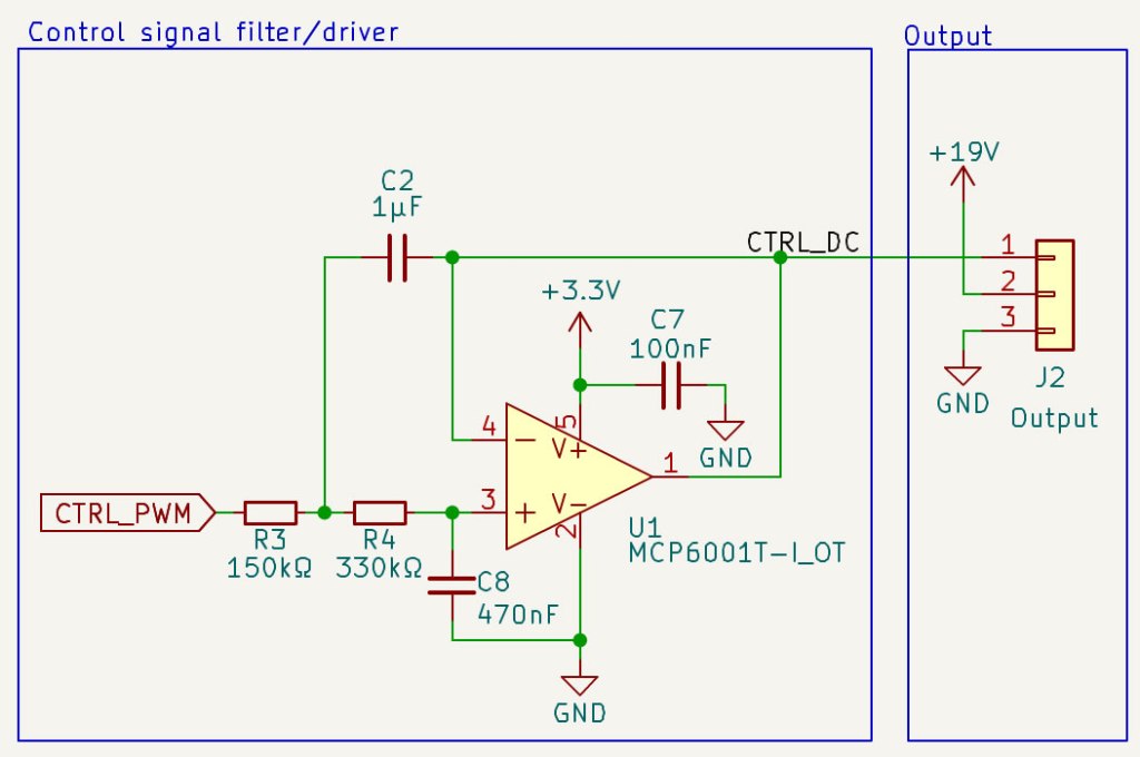
The LED driver can be controlled by PWM pulses or DC voltages. The MCU may struggle to transfer PWM through a long lamp cable. Transferring perfect square pulses requires a high (in theory infinite) bandwidth, and the cables are both capacitive and inductive. It’s easier to transfer a DC voltage. Therefore, I added an active low pass filter that transforms PWM pulses to a smooth DC.

Timer PCB design in KiCad.

Firmware is written in C/C++, using PlatformIO code editor and Arduino framework.
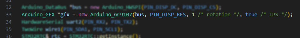
Display orientation can be changed by editing the rotation parameter in code line 33.
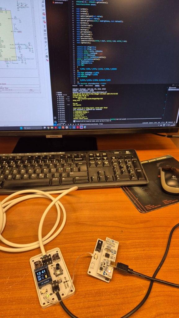
Firmware upload via a homemade ST-link USB adapter and 8-pin FFC cable.
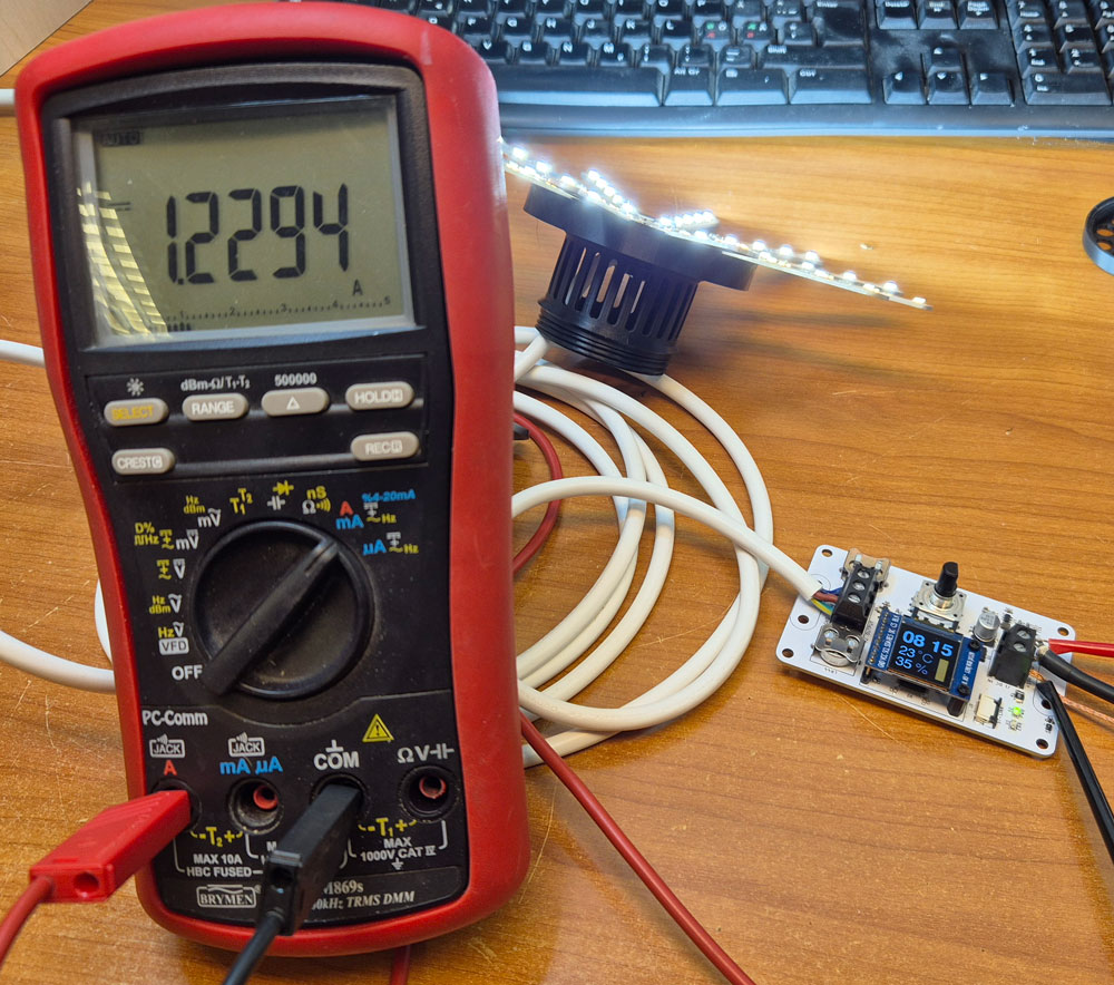
Measuring current draw from the PSU when a single lamp is driven at full brightness.
Two such lamps can be driven in parallell when a 3A laptop adapter is used as PSU.
Timer box
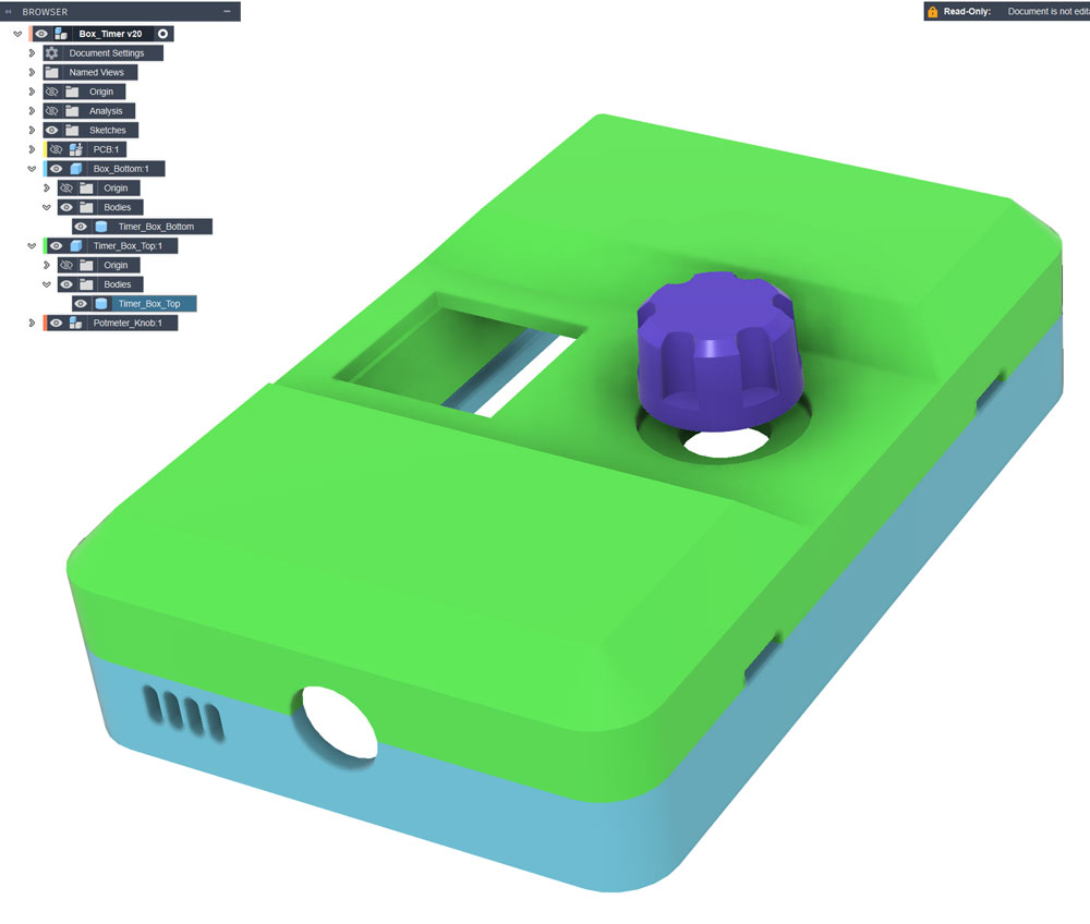
Timer box design in Fusion. Models: Timer_Box_Bottom.stl, Timer_Box_Top.stl and Knob.stl.
I also made an alternative with room for two lamp cables on the output terminal: Timer_Box_Bottom_DualOutput.stl and Timer_Box_Top_DualOutput.stl.
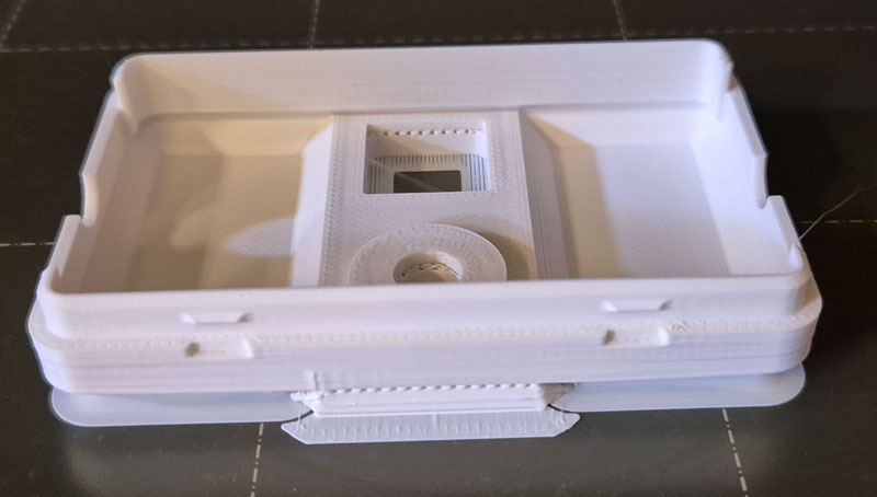
I used ASA filament for the timer box parts, because it allows surface smoothing by means of acetone vapor.
Sanding up to P800, followed by around 15 minutes in a box with paper soaked in acetone and a small fan, gives a reasonably smooth surface.

Ceiling mount with integrated cable spool
As a plant grows taller, you may need to lift the lamp by adjusting cable length. To make this possible in a discrete manner, I designed a ceiling cup with a spool onto which up to around 0.5m cable can be wound.
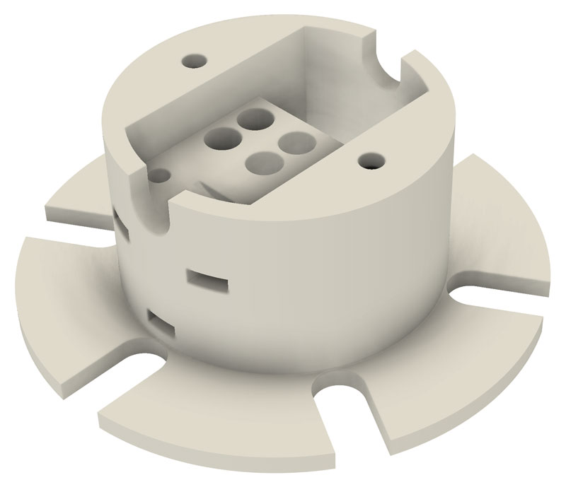
Inside the spool, there’s room for a 3-pole terminal block (Phoenix EC4 BK) for connecting lamp- and installation cable. Model: CeilingMount_CableSpool.stl
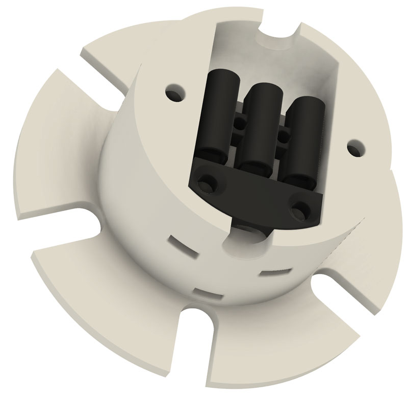
With terminal block and strain relief (CeilingMount_StrainRelief.stl).
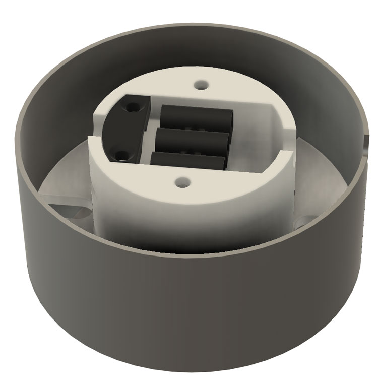
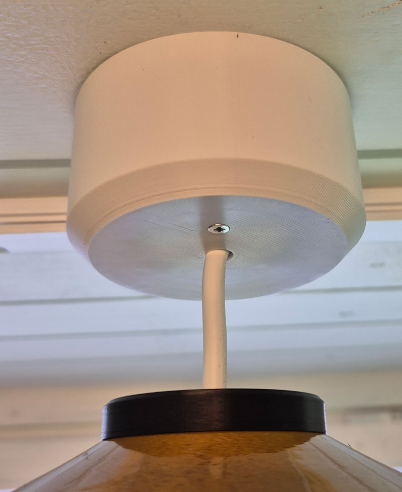
With cover attached (CeilingMount_Cover.stl).
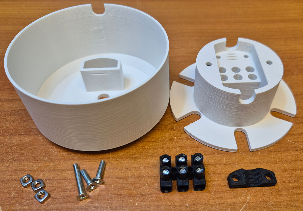
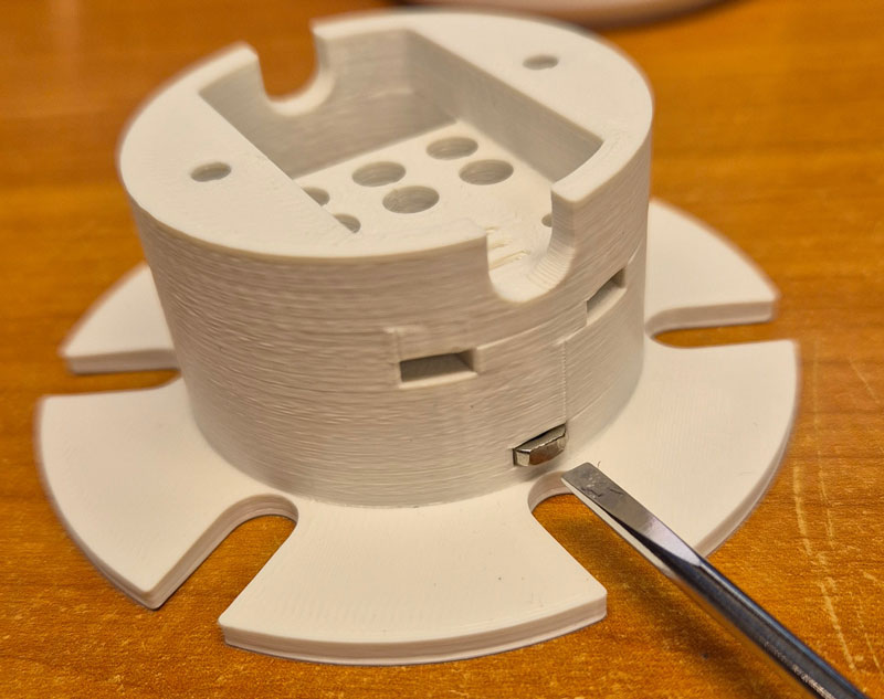
Nuts are inserted into slots on the side.
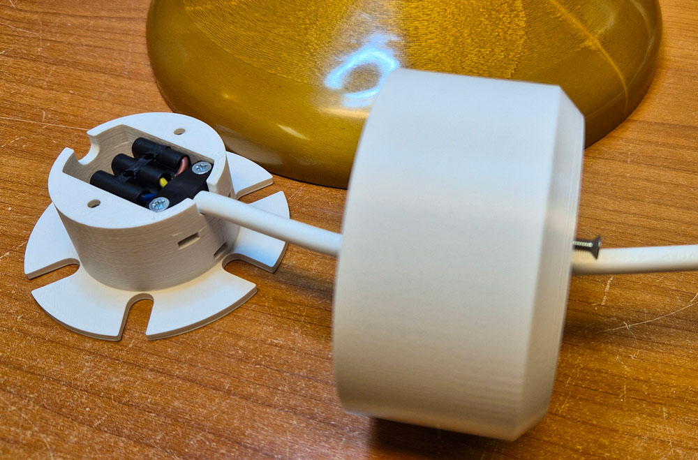
Lamp cable is threaded through the hole in center of the cover, connected to the terminal block and secured by tightening screws for the strain relief.
The longest screw will hold the cover in place.
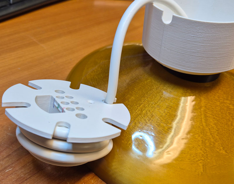
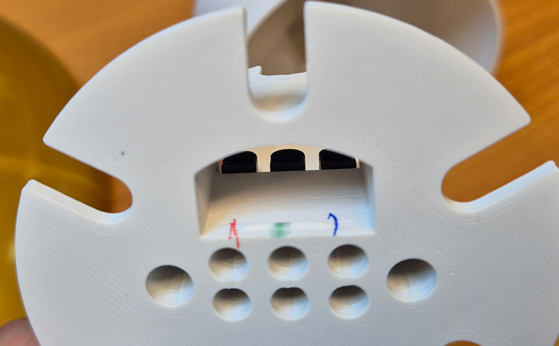
Cable spool. Markings with same colors as the lamp-and installation cable conductors can make it easier to get the connections right during installation.
Installation
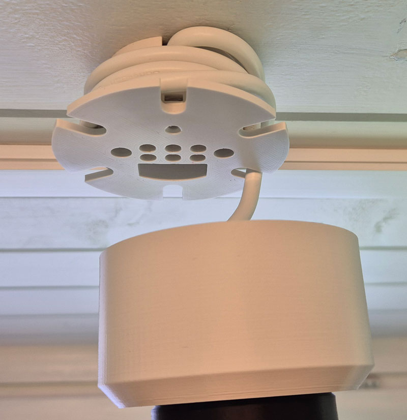
Cable spool mounted on a wooden ceiling, using two 3mm wood screws. Here the lamp cable is wound fully up to keep the lamp at its highest position.
The cable between lamps and dimmer can be hidden inside a cable duct.
With cover attached.
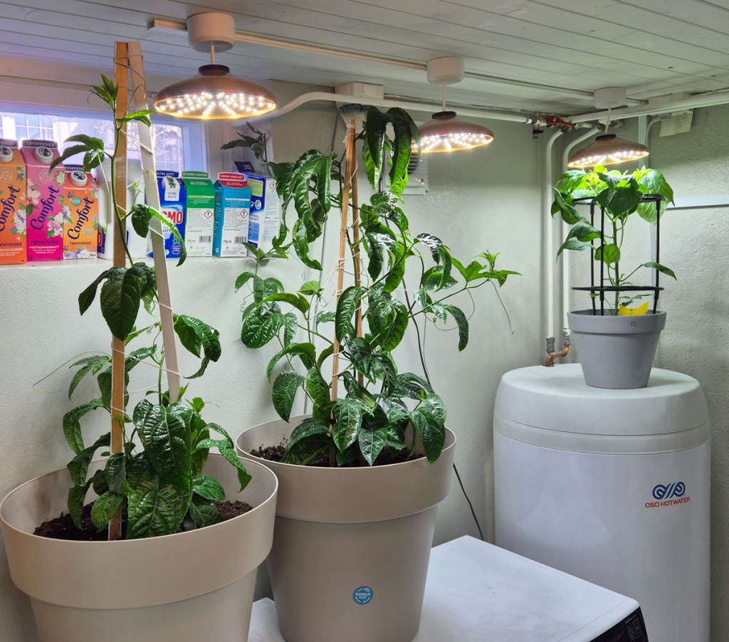
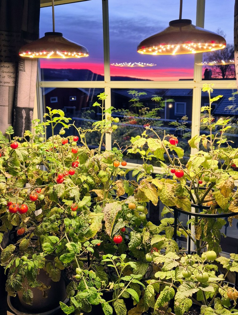
Tomatoes ripening on a windowsill in november. Here, two lamps are connected in parallell, to a timer hidden behind the curtains. The power source is a 3.5A laptop PSU.
These lamps use warm white 3000K LEDs.
Adjustment and settings
The usage should be pretty straightforward. After all, you’ve got only one button. How hard can it be 😉
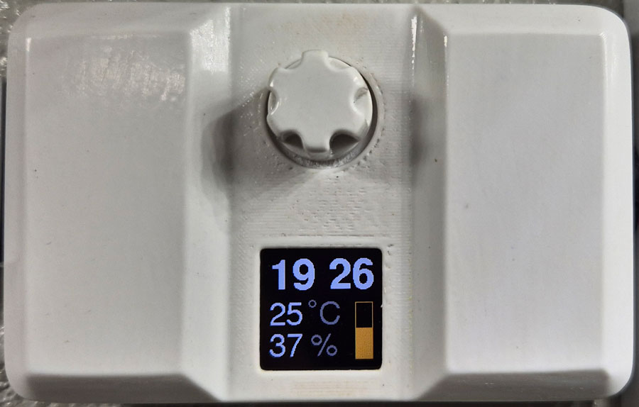
Rotate knob to adjust brightness. The brightness setting is represented by the yellow graph. Outside the timer interval for plant illumination, i.e. when lights are switched off, the graph is displayed in brown.

Press knob to enter main menu. Rotate knob to select menu item, then press to enter.
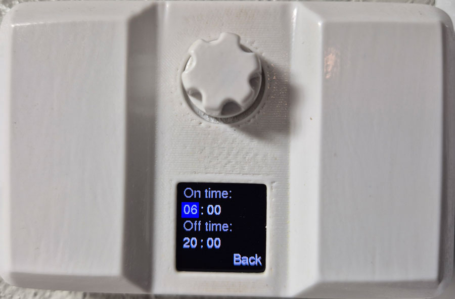
Rotate to toggle between items on the page, press to select item, rotate to change value, then press again.
Settings are stored in the MCU’s non-volatile memory, and won’t get lost during a power outage.
Brightness
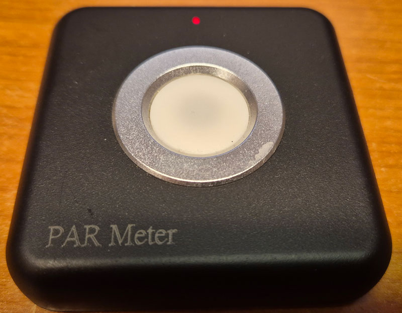
To measure plant light intensity, I bought a reasonably priced PAR meter from Amazon. This connects to your phone via bluetooth, and an app displays the measurements. I haven’t found any detailed reviews of this instrument, but those who have tested it generally report that the test results are comparable to professional PAR meters, and that’s good enough for me.
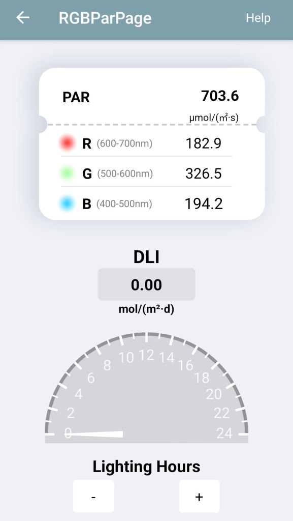
Measuring brightness 15 cm from a 5700K lamp at full brightness. The PAR meter reports around 700µmol/s/m2.

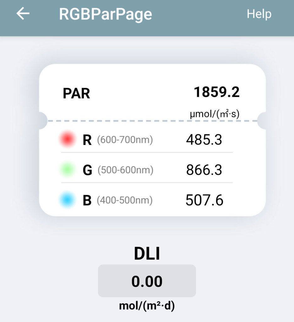
5 cm from the 5700K lamp: >1800 µmol/s/m2.
For comparison, if I point the device towards the sun at noon on a clear summer day, it reads about 2000 µmol/s/m2.
In daily use, the lamps are operated at less than full brightness.

As expected, the 3000K lamps provide light with more emphasis on red wavelengths.

Leave a comment