
When repairing or constructing audio amplifiers, I often need to test them under load, but preferably without having to listen to sine waves via a set of loudspeakers. Then, a dummy load comes in handy, and it’s simple to make: you basically just need a few load resistors and a way to keep them from overheating.
Typical speaker impedances are 4 or 8Ω, and occasionally 16Ω, so that’s what I wanted to replicate. This can be achieved using 8Ω resistors, two in parallell for 4Ω, one alone for 8Ω, and two in series for 16Ω.
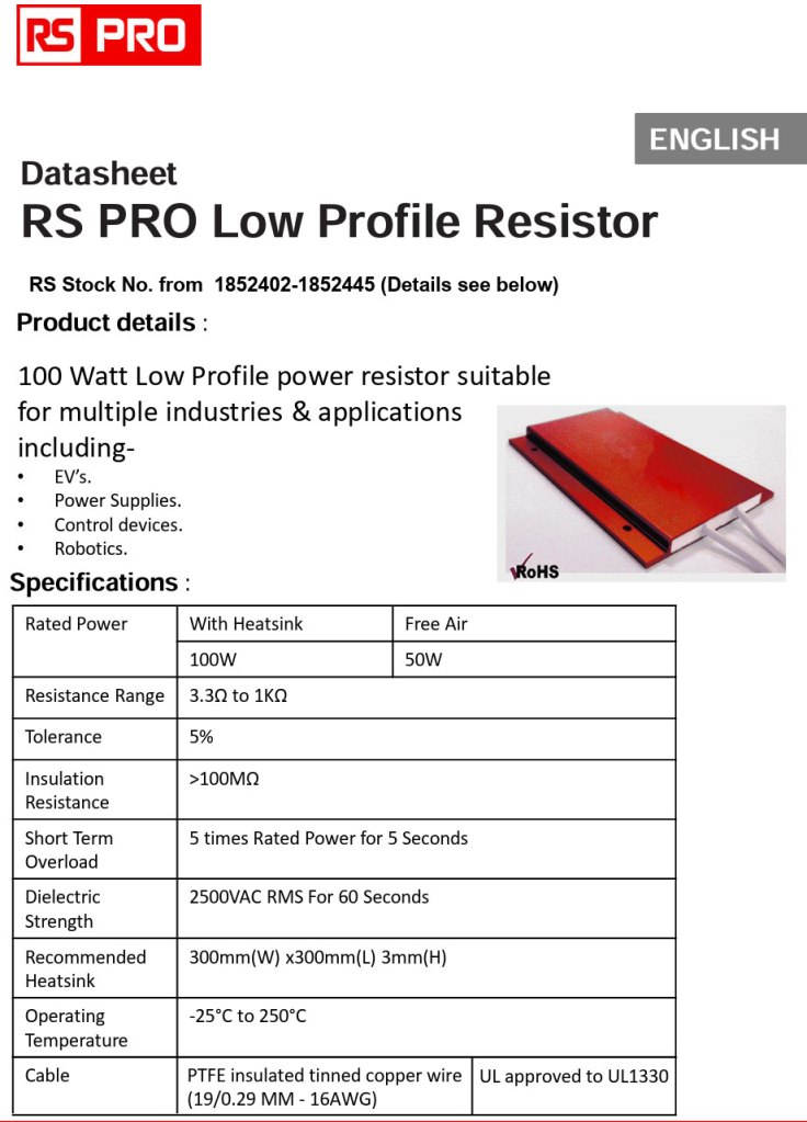
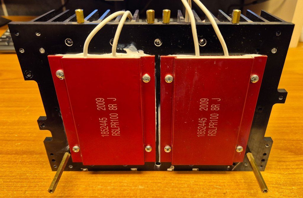
The resistors I selected for this project are 8Ω / 100W from RS, but other resistors with same resistance and a power rating that matches your needs can of course be used.
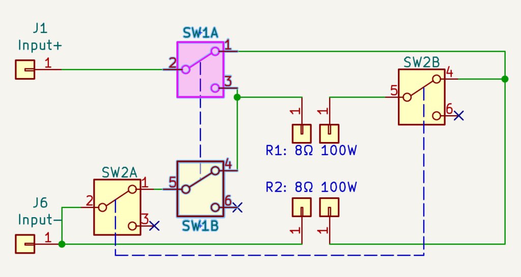
Schematic: With two 8Ω resistors and two DPDT switches, resistances of 4, 8, 16Ω plus infinity can be selected.
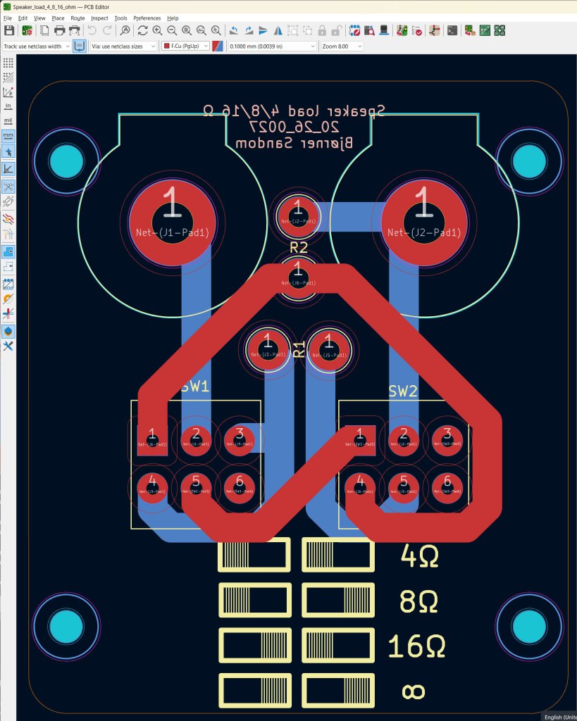
PCB Design in KiCad. Design- and production files (Gerber) are available on GitHub.
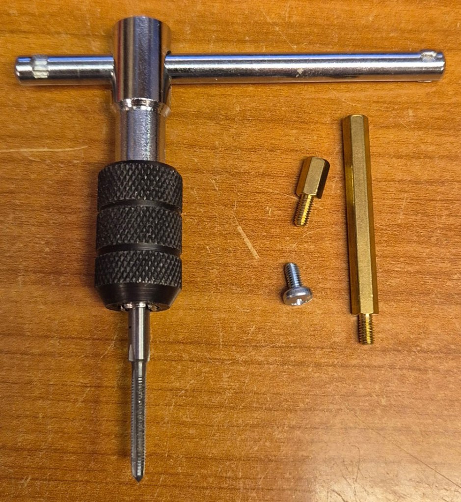
M3 tap for making threads. M3 hex spacers of 40 and 8mm length were used to tie two heatsink modules together, and mount the PCBs on top.
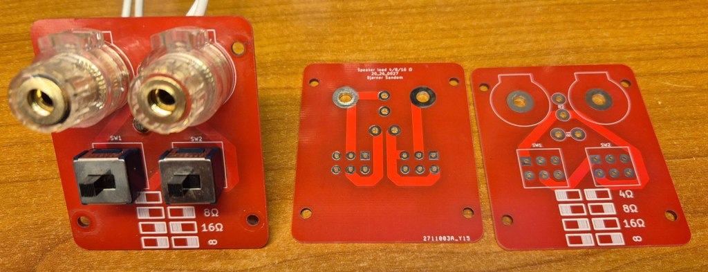
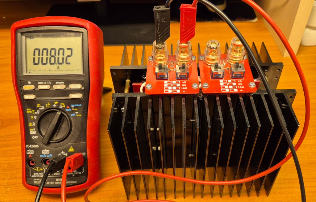
The finished stereo dummy load:

After verifying the resistance at each resistance setting, the module is ready for connecting the amplifier under test, plus oscilloscope and other test gear.

Leave a comment