
Where I live in Norway, the summers are relatively short and cold, and many plants will need a head start by germinating seeds indoors in late winter or early spring. At that time of year, there isn’t enough sunlight, so just placing the plants near a window in a heated room will not do. Artificial light is needed.
To make room for lots of plants in small room, I decided to reuse a couple of old IKEA bookshelves, approx. 75 cm wide, 25 cm deep and 2 m tall, and with adjustable shelf heights. One could of course buy ready-made lamps, but the good ones are often quite expensive, and most of them don’t fit very well in a bookshelf like this. Instead, I went for a custom solution, with Osram horticulture LEDs, dimmers for each shelf, and a timer to turn on and off the lights in the morning and evening respectively.
PCB design files (KiCad), fabrication files (Gerber), 3D models (.stl) and code for this project are shared on GitHub.
LED strips
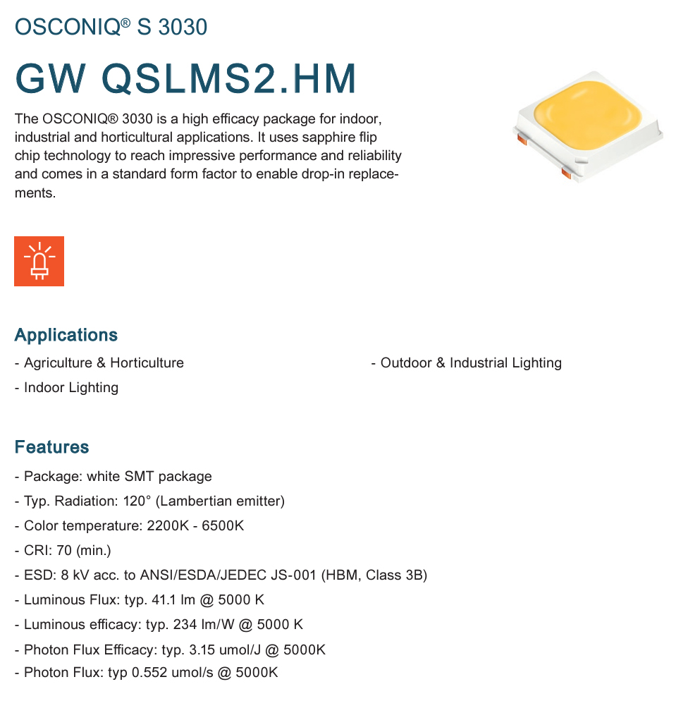
The chosen LEDs are the Osram GW QSLMS2.HM, which have a high efficacy, and which comes in a range of several different color temperatures. I went with 5700K, a cold white mix of wavelengths resembling daylight.
Achieving sufficient light takes a lot of such LEDs. Different types of plants at various growth stages require different amounts of light. A plant’s need for light is commonly measured in µmol/m2/s, which is the number of photosynthetically active photons (400-700 nm) reaching a certain surface area per second. 1 µmol = 6.022×10¹⁷ photons. A typical value for seedlings is 150 µmol/m2/s, small herbs like basil needs around 230 µmol/m2/s in the growth face, chili requires at least 300 µmol/m2/s, and tomatoes demand more than 500 µmol/m2/s to set fruits.
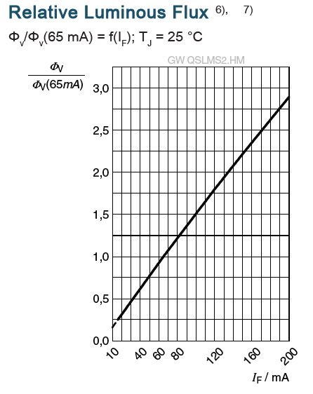
The LED datasheet indicates a luminous flux of 41 lm at 65 mA forward current, and a photon flux of 0.55µmol/s . We don’t want to drive the LEDs at their rated max current of 200mA, but 150 mA is expected to be fine. The datasheet doesn’t explicitly mention photon flux for different currents, but this graph shows that the luminous flux increases almost linearly with current, so I assume that this also applies to photon flux. A modest estimate is 1 µmol/s per LED when driven at 150 mA. 60 LEDs will then provide 60 µmol/s.
The shelf area is 0.25m*0.75m≈ 0.2m2. When the space between each shelf level is adjusted so that 60 LEDs illuminate 0.2m2, the intensity should be around 300 µmol/m2/s; more than enough for seedlings, and sufficient for growing various plants.
To provide heat dissipation, the LEDs were mounted on aluminium PCBs. I decided to make LED strips, each with 5 LEDs connected in series. The total voltage drop is 5 x 2.8V at 150mA, a total of 14V. For each shelf plate, I connected 12 strips in parallell, and the total current draw per shelf plate is 1.8A. The resistors help to even out any current deviations between each LED strip, which otherwise might occur due to small variations in each LED’s forward voltage.

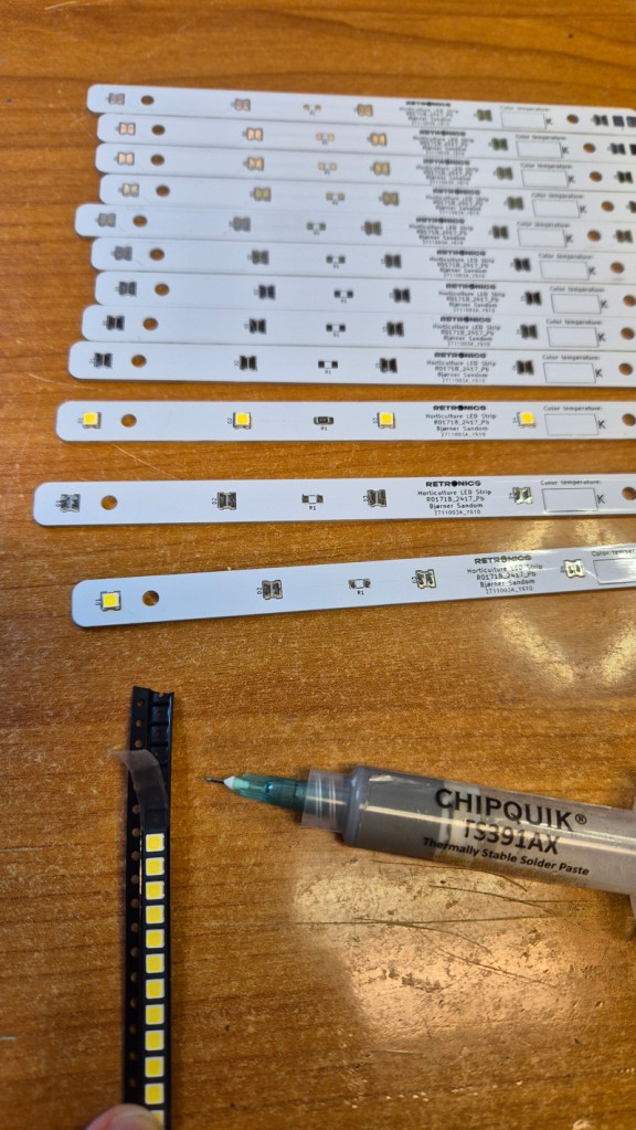
The LED strips can be assembled with solder paste and a hot plate like this, or in a reflow oven.

LED drivers/dimmers
Basic commercial plant lights usually come with fixed brightness. I thought it would be better with a dimmer for each shelf plate, to allow different brightness for various plant types and growth stages.

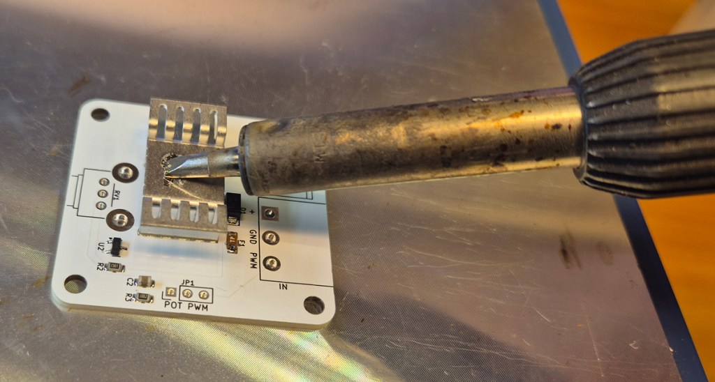
The dimmers are based on AL8843 LED driver ICs, which work pretty much like buck converters, except they have adjustable constant current output instead of constant voltage. I designed the circuit so that output current (and LED brightness) can be adjusted with either a potentiometer or by PWM pulses from a microcontroller, selectable with a jumper. For this plant shelf, the potentiometer option is used, and a jumper is placed on the “Pot” position of the pin header. Max output current of the dimmer can be set by R1. For this project I’m using 12 LED strips in parallell, each carrying up to 150mA. The max current we want the dimmer to deliver is 12*150mA=1.8A. When the potentiometer is rotated fully clockwise for max brightness, the AL8843 will keep 0.1V over R1, hence this resistor’s value was calculated as 0.1V/Imax = 0.1V/1.8A = 56mΩ. If you’ve got a smaller shelf and want fewer LED strips, just calculate R1 accordingly.

The hot plate set at 200°C wasn’t sufficient to melt the solder paste under the heatsink, so I helped it out with a soldering iron.
Power source
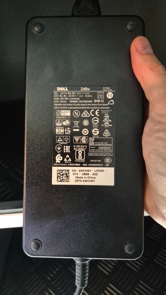
A couple of 19.5V / 12.3A power adapters, reused from scrapped laptops, were used to power the LEDs.
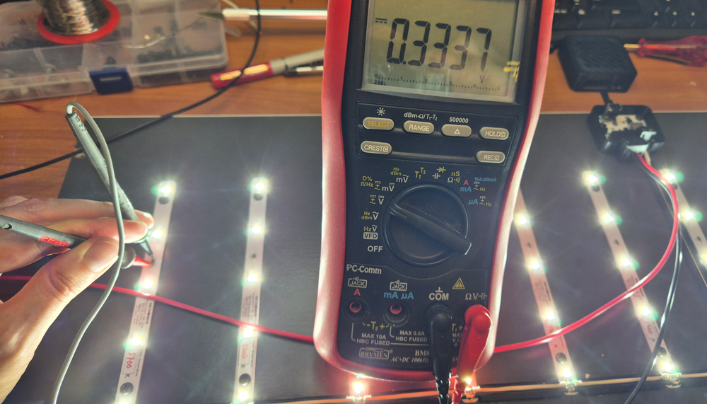
When driving a single shelf plate with 60 LEDs at a total of 1.8 A (dimmer set to max), the current draw from the power adapter is a little less than 1.5 A, so in theory each such PSU can deliver enough power for 8 shelf plates à 60 LEDs. For this project, I’m using up to 6 shelf plates per PSU, keeping the power adapters well within their comfort zone.
Note: standard power adapters for smaller laptops commonly deliver only around 3.3 A, sufficient for two such shelf plates.
Timers
To simulate day and night, the plant lights need to be turned on and off at certain intervals. I designed custom STM32-based timers with high-power MOSFET outputs (click to expand):
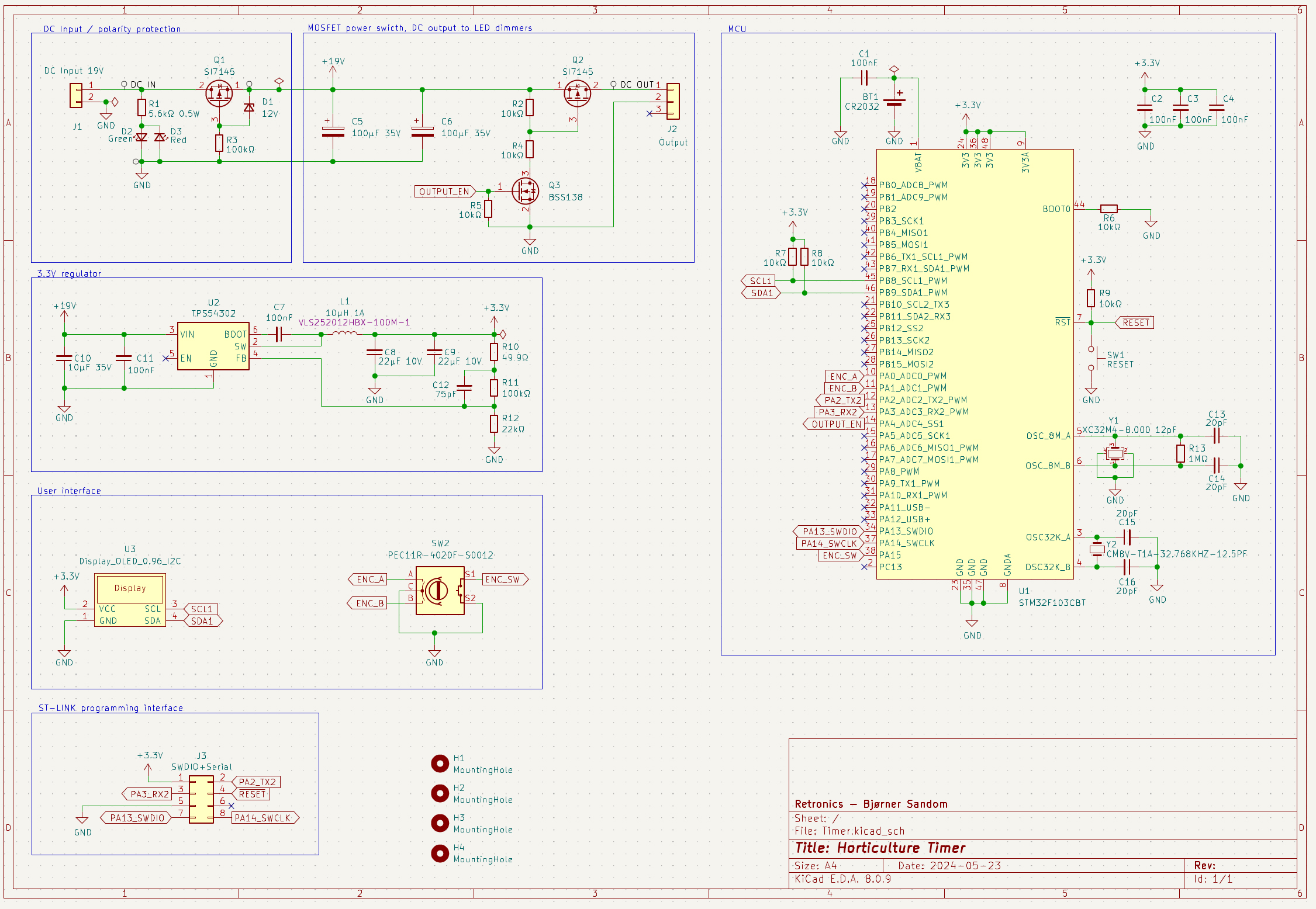
On the DC input from the aforementioned laptop PSUs, there is a polarity protection circuit. If you should happen to reverse the polarity from the PSU, a red LED will shine, and the rest of the circuit is unaffected. An STM32F103CBT microcontroller with integrated real-time clock keeps track of time, which is presented in an OLED display. Actual time and LED on/off time is adjustable with a rotary encoder. Settings are stored in non-volatile memory of the STM32, and a battery keeps the real-time clock alive during power outages.
The SI7145 MOSFETS have an on-resistance of only 2.6 mΩ, ensuring very low voltage loss even at fairly high currents. In theory SI7145 can handle up to 60A (when properly cooled). I’ve tested this circuit up to 10 A load, and with this current the power dissipation of each MOSFET is only about 1/4 W, which can easily be handled by small copper pours on the PCB.

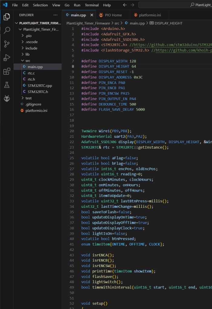
The code is written in C/C++, using PlatformIO with Arduino framework, and the STM32 is programmed via a custom ST-LINK interface. Other ST-LINK adapters will also work, provided you get the pinout right.
Assembly


LED dimmer mounted inside 3D printed part LED_Driver_Box_Bottom.stl, and attached to the shelf plate with screws. All 12 LED strips on the plate were soldered in parallell, using 0.75mm2 hook-up wire. A longer wire guide (WireGuide_145.stl) is glued along one of the middle LED strips.
The two wire holders (WireClip.stl) are for attaching hook-up wire to the Timer later.


Left: One of the plant shelves, with 4 illuminated shelf levels installed (the picture shows an earlier version with 8 LED strips per shelf plate).
Below: Growing physalis and strawberries indoors during winter.


Leave a comment