
There are lots of breadboard power supplies available on the market, but almost all of them seem to be based on linear voltage regulators like 7805 or LM317, and with their tiny heatsinks the output current and input voltage is very limited. To get smal yet powerful PSU, I had to make one, and I might as well share the design files with you.
My requirements for the PSU:
- It must be able to deliver 3.3 and 5V simultaneously.
- It must handle an input voltage range of at least 6-18V.
- It must be able to deliver at least 1A output current, at any input voltage within the given range.
- The DC input must be polarity protected.
- The outputs must have short-circuit protection.
- It must be possible to run the PSU from a USB power source.
- The PSU board must fit into breadboard power rails, and the PCB must be very compact.
I came up with the following circuit:

On the DC input, there is a reverse voltage protection, based on this concept. If you accidently swap the + and – terminal, a red LED will shine, while the rest of the circuitry is safe. The DC connector is a pluggable terminal block, which can be bought from e.g. LCSC.com: this and this.
The DC conversion from 6-20V input to 3.3V and 5V outputs is performed by two TPS54302 buck converters, which come in tiny SOT-23 packages, and despite their small size, they can deliver up to 3A output current, provided that the PCB has sufficient copper area for heat sinking. Extra filtering with ferrite beads and capacitors contribute to reduce ripple/noise. On the output of the 5V regulator, there is a reverse current protection circuit, to prevent the buck converter circuit from interfering with USB 5V bus, when USB is used as DC input.
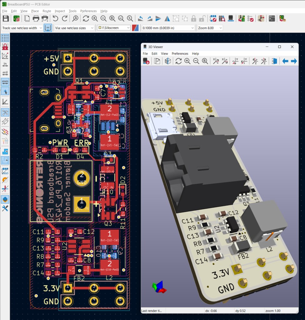
PCB design in KiCad. Design files and PCB production files (Gerber) are shared on Github.
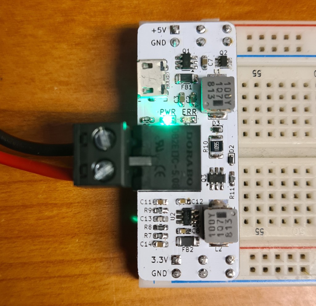
The finished PSU, mounted on a breadboard, and powered from a LAB PSU.
With a board size of only 2x5cm, the unit doesn’t occupy much space.
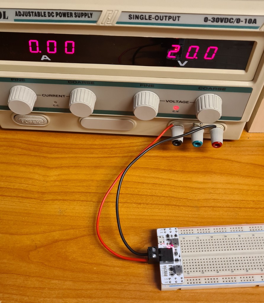
Testing the input polarity protection. 20V is applied in reverse. The red “ERR” LED is lit, but nothing else happens.
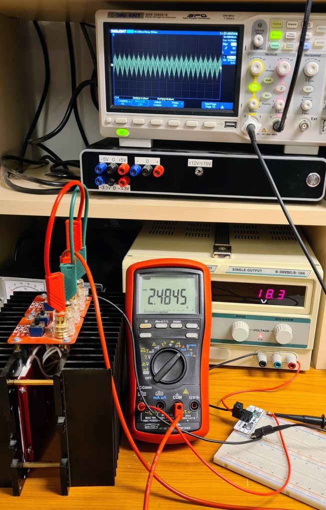
Measuring output current and ripple voltage from the 5V output, while connected to a dummy load.
With 2A current draw, the breadboard PSU is stable. At 2.5A, the buck converter chip still delivers 5V, but after a while it starts to overheat and periodically shuts down.
With a larger PCB (larger copper pours for heat dissipation), it might be possible to increase the current to 3A, but such high currents are not suitable breadboards anyway. 2A (total for the two outputs) is plenty for this purpose.
If the output is shorted, the buck converter reduces the output voltage to a minimum, but immediately returns to 5V when the short circuit is removed.


Leave a comment