
Warning! This project involves working with dangerously high voltages. Don’t try this if you don’t know how to work safely with electricity.
When repairing vacuum tube devices like radios or amplifiers, or switch mode power supplies, you may often need to discharge capacitors of fairly high voltage (several hundred volts).

Some daredevils short the capacitors with e.g. a screwdriver, releasing all the stored energy as a giant spark.
A more sensible way is to discharge the cap through a power resistor. Holding it like in this picture is, however, not recommended.
To verify that the cap is discharged, you’re probably using a voltmeter, and maybe you’ll have to repeat the discharge process.

There are several different discharger devices available on the market, and I bought this one from AliExpress. This seemed like a good offer (99 NOK equals 9 USD).


Here it’s being tested on a 180µF cap, charged to 350V. And the discharger does work. The problem is it works very slowly, taking about 90 seconds before the LED fades out. Then, the remaining voltage is approx. 8V.
In the beginning, when voltage is high, the LED is unpleasantly bright, and at lower voltages the light is barely visible.
There are two LEDs. Which one of them is lit depends on how you connected the polarity.
Can the “Intellect Capacitor Discharger” simply be LEDs connected in series with a high value resistor?

When opening the box, suspicion is quickly confirmed: this is just two LEDs in antiparallel, connected in series with a 100kΩ resistor. With such high resistance, it’s no wonder discharging is slow.

As we can see, they’ve also used the cheapest and crappiest connectors available. The included probes didn’t look too bad, and may be used as replacements for a multimeter, and I also got a 100kΩ/8W resistor plus a plastic box which may be reused. Apart from that, what I got is junk.
After that disappointment, it was time to make something better. Discharge time must be significantly reduced, and it would be better if the LED would shine at a relatively constant brightness during discharge. The circuit I came up with is this:

Some calculations: lets say a capacitor is charged to 600V, and then discharged through this circuit. The initial current is (600V-5V)/(3*3.3kΩ)=60mA. For each power resistor, this causes a heat dissipation of I2R=12W. This, however, is just briefly, since the capacitor voltage decreases rapidly at first. I used these wirewound resistors, which are rated for 5W continuously (when surrounded by free air), but which can handle much higher power for short durations. The peak power dissipation in the zener diodes is 4.3V*60mA=258mW, about half of their max rating.

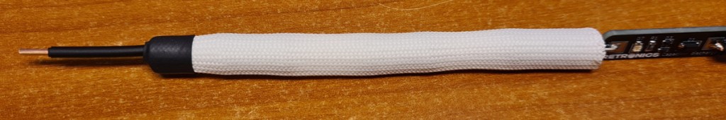
All components, except the power resistors, were fitted on PCB only 7.5mm wide. Why? Because I want the discharger tool to be shaped as a pen.


With a 560µF cap, the discharge time was 36 seconds, and the resistors felt hand warm. I will typically use the discharge pen for broadcast receivers, where the total capacitance is only a fraction of that, so I do not worry about heat or discharge time. For large tube amps or switch mode power supplies, there may be capacitors of 1000µF or more, and in those cases I will rather use a more powerful discharger, which will be subject for my next post.

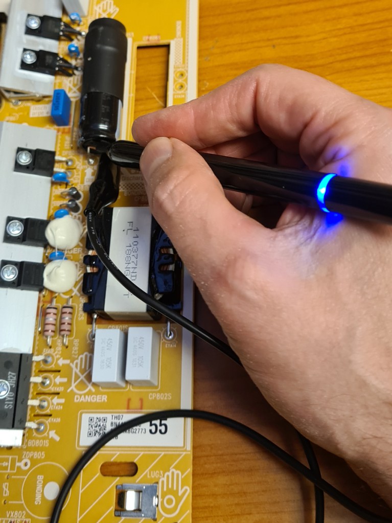
Since my homemade PSU only goes up to about 350V, higher voltage testing was performed by connecting 2 capacitors in series and charging them independently.
Here are two 270µF caps in series, each charged to a little over 300V. This gives a total of 135µF and 600V. Discharge time is about 10 secs, and there is no noticeable heat from the power resistors.
I probably could have connected a third cap in series to add up to an even higher voltage, but I don’t expect to work with any radio, amp or SMPS with voltages higher than 600V, so let’s just say the max voltage for the discharger pen is 600V.

The “pen” was modelled in Fusion 360, 13cm long, and with an inner diameter of 8mm. At one end, it is pointy, and at the other end there is a plug with a hole for the wire.

Printing a tall and slim object like this required a brim. I mainly used black ASA, but 26mm from the bottom I added a filament change to translucent blue ABS, so that the LEDs can shine through. At 28mm, the filament was changed back to black ASA.


Design files (KiCad), PCB production files (Gerber) and 3D models (.stl) are shared on Github.

Leave a reply to Aleksandar Kotsev Cancel reply