
When soldering and inspecting small SMD components, a microscope is indispensable, and for this purpose I bought an AD407, which has great image quality for a reasonable price; currently $199 at Amazon (https://www.amazon.com/gp/product/B07VK52X9C/).

It has a 4 megapixel image sensor, decent optics and a built-in 7″ LCD screen, plus HDMI output for connecting an external monitor, and an SD card slot for saving snapshots or video. The unit is attached to a steel base with adjustable height. There are two LED spotlights with flexible arms. There is also an infrared remote control (which I hardly ever use).
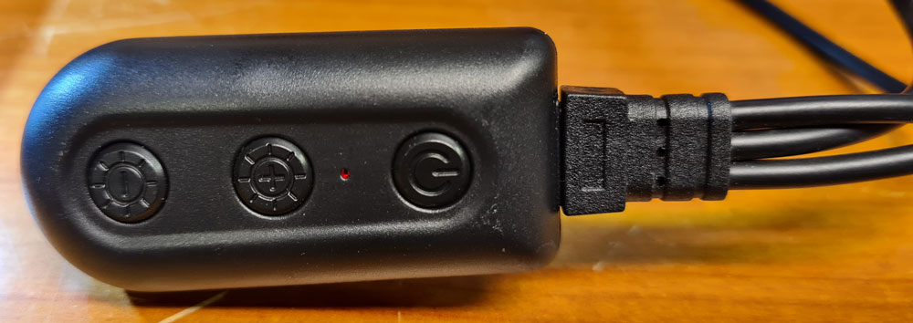
The microscope and LED spots are powered by a USB charger.
A unit attached to the USB cable contains On/off switch and LED brightness adjustment. This makes a mess of cables, and is quite annoying.
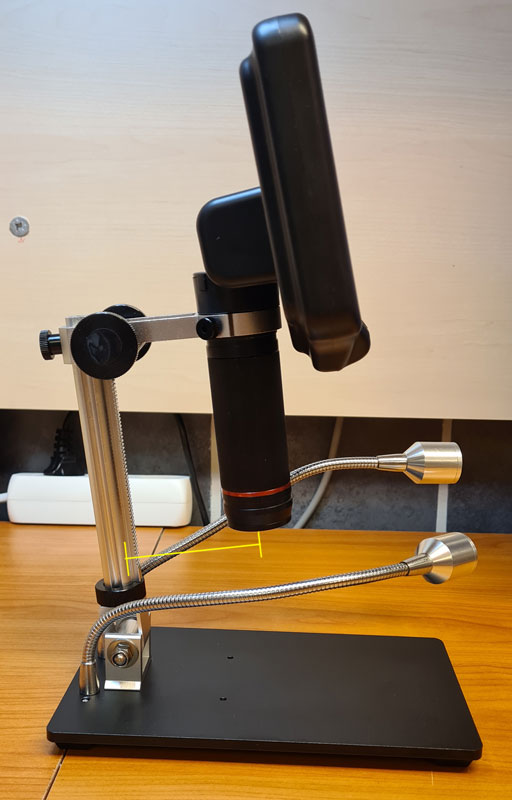
One significant drawback is the limited space between the base mast and the camera, which means the microscope is only suitable for inspecting smaller PCBs. The base platform is also quite small, with little support to keep the PCBs steady. Andonstar now also sells the AD407 Pro, which has an improved base with more space between the mast and the camera, allowing larger PCBs to be viewed.
The LED illumination is decent, but I often find myself adjusting the flexible arms back and forth / from side to side, to get a good light angle, thinking that it sometimes might be better with a fixed, wide-angle light source pointing downwards, e.g. a LED ring mounted around the lens.
All in all, I’m satisfied with this product (when the reasonable price is taken into consideration), but I decided to make some changes to improve the usability.
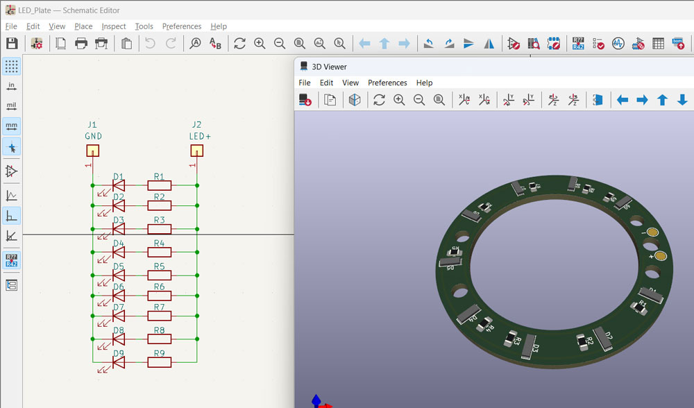
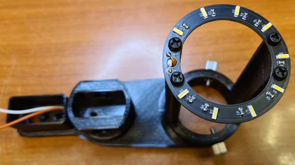
I designed an extension mount which increases the space between the base mast and the camera lens, and allows a LED ring to be mount around the lens. When extending the camera’s distance from the base, the LED arms would be to short from their default position, so I decided to mount them to this extender instead.

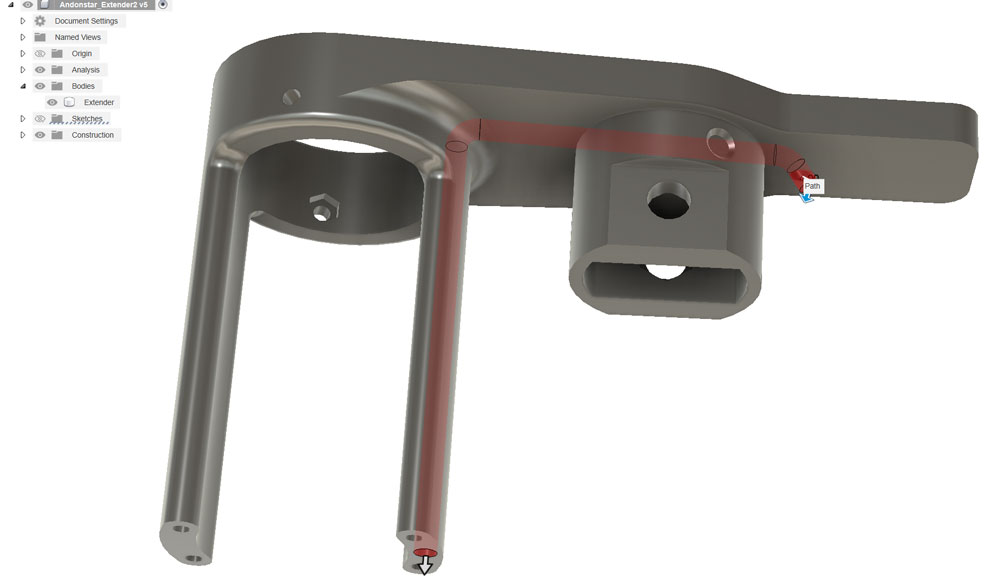
Inside the extender, there are pipes for hiding wires. Here, the pipe for the LED ring supply wires is shown in red.
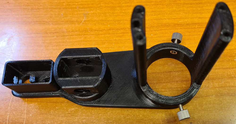
The extender was printed using Prusament PETG, but other strong filaments like ASA will also work fine.
M3 nuts and thumbscrews are inserted as shown. These will lock the camera lens in place.
For the LED ring, I used a total of 9 fairly high brightness (11 cd) LEDs in 4014 package and 6500K color temperature: Osram KW DPLS32.EC-6H6J–4C8E-1. Warm white LEDs are not recommended, since they make everything appear yellow on the microscope screen (yes, I’ve tried). Separate drop resistors for each LED compensates for any discrepancies in the individual LEDs’ forward voltages, which could otherwise cause differences in LED power and brightness.
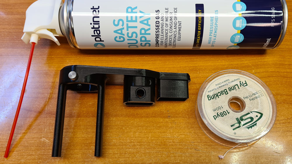
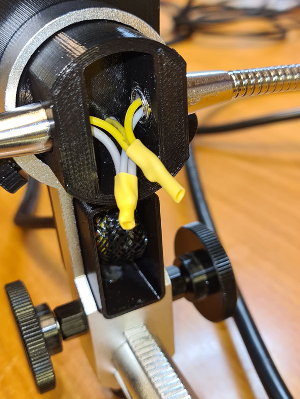
Pulling wires through the narrow and bent pipes in the extender takes a special technique. I used compressed air, and a string to which I tied a tiny piece of cloth.
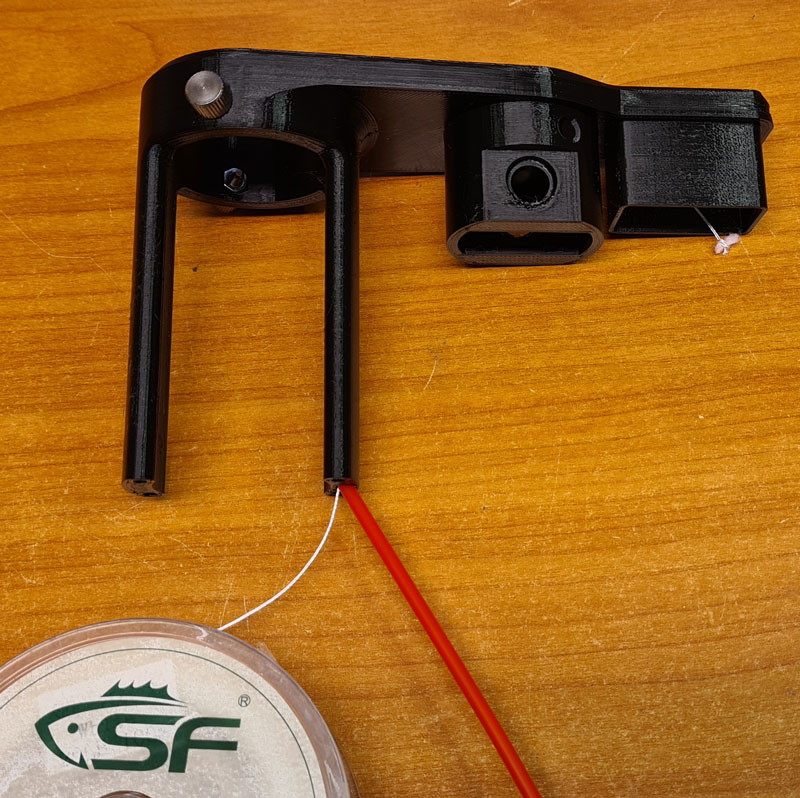
Insert the string with the cloth piece into one end of the pipe, blow with compressed air, and the string instantly comes out on the other end.

Tie two wires to the string, and pull the string ’till the wires come through the pipe. I used 26 AWG stranded core wires with silicone sheath, which are flexible and handles the current with no significant loss. The wires must be long enough to be passed alongside the base mast, down to a dimmer on the base platform, so don’t cut them yet.
Orange-White (LED ring +/-), Yellow-Gray (LED spotlights +/-), Red-Black (5V/GND, both for PSU and USB connector).

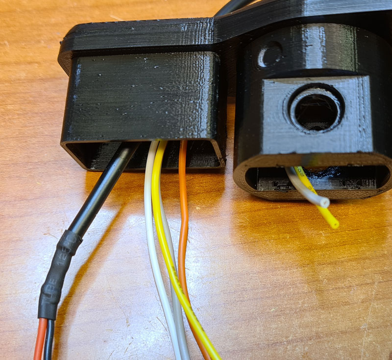
A second layer of heat shrink is used around the USB cable, and is thick enough to prevent the USB cable from getting pulled out of the tight hole in the extender.
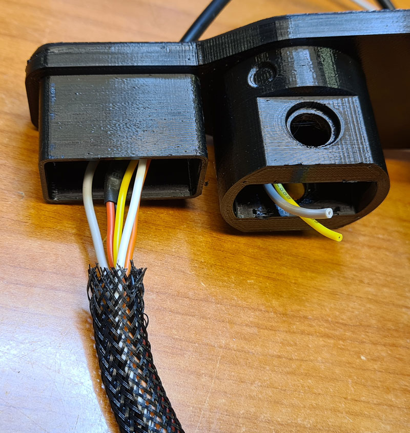
A braided hose of approx. 8mm outer diameter is used for hiding the wires.
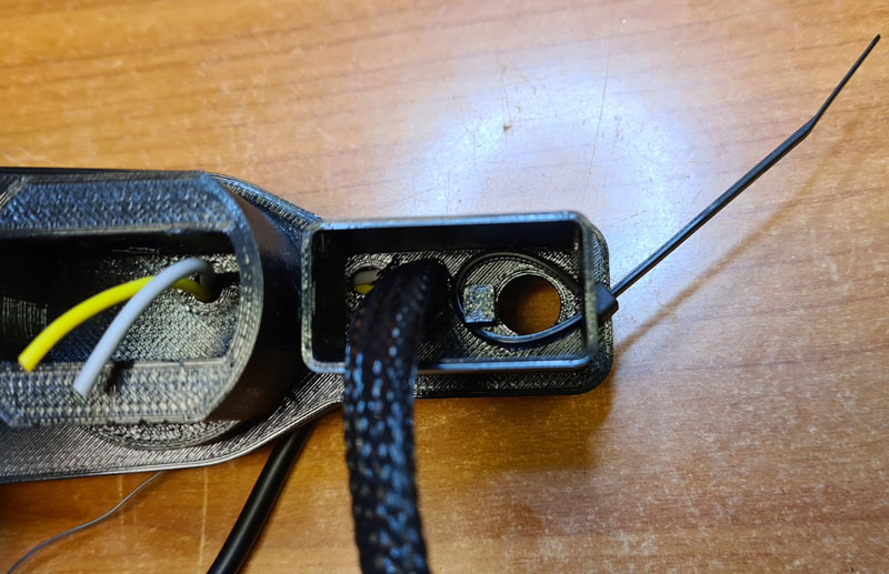
A zip tie is placed as shown in the picture. Don’t tighten it yet.
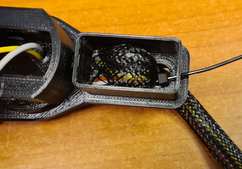
Pull the braided hose through zip tie loop and the larger hole of the extender, as shown. Now you may tighten the zip tie and cut off its excess.

Before mounting the LED arms, attach the plastic extender to the Andonstar base, and use the original thumb screws to lock it in place. The original wires in the LED arms are of poor quality, and are likely to break when bent a couple of times, so I replaced them with 26 AWG silicone wire. I was unable to find the perfect nuts to match the arms’ thread size, but these are close enough.
Attach the LED arms to the extender, and tighten them against the nuts. Solder the wires together and use heat shrink for insulation.

Put the lids on.
3D models (stl) and PCB fabrication files (Gerber) published to Github: https://github.com/donpivo/Andonstar_Extensions
Continue to Part 2 for base platform extension, power supply and LED dimmer…

Leave a comment