
It’s been a long detour from soldering the µTracer kit, to actually start using the instrument, but I’ve learned a lot along the way, and I’m quite pleased with the result.
Since I don’t have access to any high-end test gear to use as reference when testing the µTracer, I cannot review it’s accuracy. What I can do, however, is to run tests on brand new vacuum tubes, and compare the test results/curve traces with the respective datasheets, to get an impression of whether the µTracer works as expected.
µTracer can perform traces of almost any combination of parameters. In this video, an EL84 is used as test object, and anode current is drawn as a function of anode voltage in the interval from 2-300V, with screen grid kept at a constant 250V, and with control grid being stepped from -10 to 0V:
Prior to the traces to begin, I’m turning on the output from the custom heater PSU by clicking the “Heater on!” button in the µTracer software, and giving the tube a little time to heat up (usually a little longer than in this video). Notice how the current limiter kicks in when the filament is cold, and gives the tube a soft start, before entering constant voltage mode.
The finished trace, compared to the plate characteristic chart in the datasheet. The results seem to match pretty well.
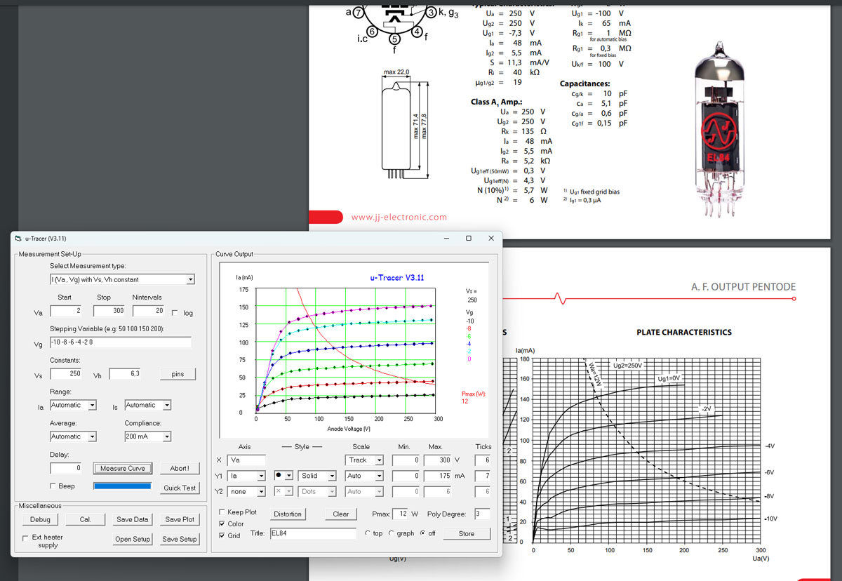
Some will notice that the trace periodically goes beyond the max anode dissipation of 12W. This is not a problem, since the measurements are performed in pulses of about 1ms, and not a continuous current, hence the anode will not turn red hot.
Curve tracing may take some time, depending on your selected parameters. Luckily, the µTracer also offers reasonably quick tests of e.g. transconductance at a selected bias point:

I’ve just started to use the µTracer, but my impression so far, is that µTracer is an incredibly versatile instrument, which has the capabilities I need for testing tubes in broadcast receivers and audio amplifiers. The µTracer3+ provides anode and screen grid voltages up to 400V, and currents up to 200mA. Sometimes I may test tubes with higher voltage rating than that, but 400V is sufficient to get a good impression of the tube characteristics.
For those who need higher voltage and current capabilities, the larger model µTracer6 is able to deliver up to 1000V and 1A: https://www.dos4ever.com/uTracer3/uTracer3_pag11.html
One thing that could improve usability of the software, would be an integrated database with characteristics, pinout and test parameters for most common vacuum tubes.
Preliminary verdict
Despite some drawbacks and limitations, like the obsolete RS232 interface and the built-in PWM heater PSU, µTracer offers outstanding value for money. The kit is easy to build and calibrate, thanks to the thorough constructors- and users manuals.
µTracer does not pretend to be a high-end test instrument for professionals, but for hobbyists like me, with a tight budget, µTracer is probably the best alternative on the market today.

Leave a reply to Robin Bowes Cancel reply