
One requirement for the heater supply module, is to present real-time measurements of the heater voltage and current. There are essentially three parts needed: a measurement device, a display and a microcontroller.
For a quite simple circuit like this, the trusty old ATMEGA328P, known from basic Arduino boards, is up for the job. I might use this MCU’s internal ADC to measure voltage and current, but for higher precision + ripple immunity, I chose the INA219 programmable power monitor, which measures voltage and current (over a given shunt resistor), communicates via I2C, and comes in a tiny SOT23-8 package.
I programmed this device to perform 32 samples of voltage and current over 17ms periods, and calculate the average values, to filter out any spurious values that might come from SMPS ripple/noise. 4 times a second, the ATMEGA asks the INA219 for updates values, and presents them in a 1.3″ display with SPI interface.
The circuit:
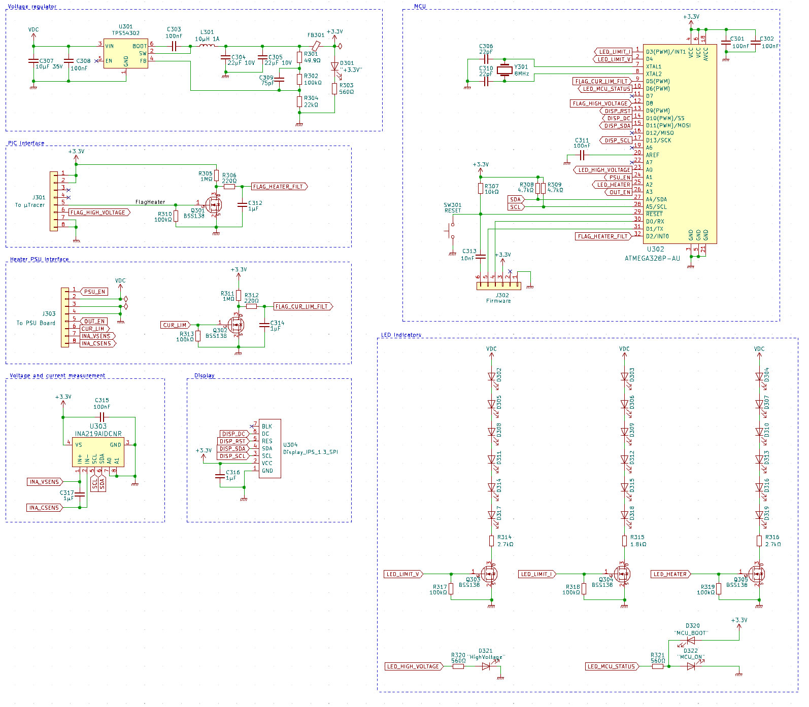
This board receives 19.5V from the heater PSU board, and a switched regulator based on TPS54302 steps it down to 3.3V for the circuitry.
From the USB interface module described in this post, there are two signal lines:
- One from the µTracer PIC heater PWM pin. This enables the ATMEGA to listen for PWM pulses, which indicate that heating has been turned on from the µTracer software. The PWM signal is filtered to a stable value by Q301 and surrounding circuitry.
- One from the “high voltage” LED pin on the PIC. This notifies that high voltage is present in the µTracer circuit.
On the pin header towards the heater PSU board, there are several signal lines:
- PSU_EN: Lets the ATMEGA switch the XL4005 on and off.
- OUT_EN: Turns on/off the output voltage from the heater PSU.
- CUR_LIM: Notifies the ATMEGA when the current limiter kicks in.
- INA_VSENS: Lets INA219 sense the output voltage from XL4005.
- INA_CSENS: Lets INA219 sense the voltage over the shunt resistor, and thereby calculate the current draw.
The ATMEGA also controls status LEDs for voltage current and heater output, which will be mentioned in the next post. Before soldering the microcontroller, you need to burn bootloader.
Finished measurement and controller board (front and back), ready to be connected on top of the heater PSU board:


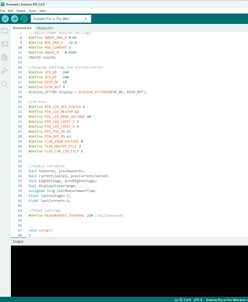
Firmware for the ATMEGA is written in Arduino IDE. This is posted to the GitHub repository for this project, and can be uploaded via a USB-to-UART adapter (FTDI adapter), connected to the Firmware port of the MCU board.
In the next post, the heater PSU performance will be tested.

Leave a reply to vincenzo Cancel reply