
When designing a heater PSU which is to be integrated with a µTracer, I had the following requirements:
- The voltage shall be selectable in steps for the most used heater voltages: 1.5V, 5V, 6.3V and 12.6V.
- I addition, the voltage shall be steplessly adjustable up to at least 15V.
- It shall be possible to adjust the voltage both before- and when the heater output is turned on.
- The PSU must be able to delivery enough current for all tube types that I’m likely to test. 2.5A will be sufficient.
- There shall be an adjustable current limit, to protect the circuit from overcurrent situations.
- It shall be clearly visible for the user when the current limit is the limiting factor of the output voltage.
- It shall be possible to “soft start” the tube heaters, i.e. gradually increase the voltage as the filaments heat up and gain higher resistance.
- At all loads, the output voltage shall be kept well within +/- 5% of the nominal value.
- The shall be a built-in voltmeter and amperemeter.
- It shall be possible to use the tube tester for tubes with directly heated cathode.
- The unit shall be compact enough to fit in the small enclosure I’ve chosen for this project.
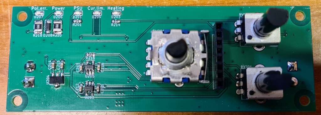
I decided to split the functionality to two interconnected PCB boards: One for the switched heater supply, and one for displaying voltage, current and status information. The rest of this post is about the heater supply.
The voltage regulator circuit is based on the XL4005, which has pretty much the same specs as XL4015, except that the internal voltage reference is 0.8V. After experimenting with different solutions, this is the circuit I came up with:
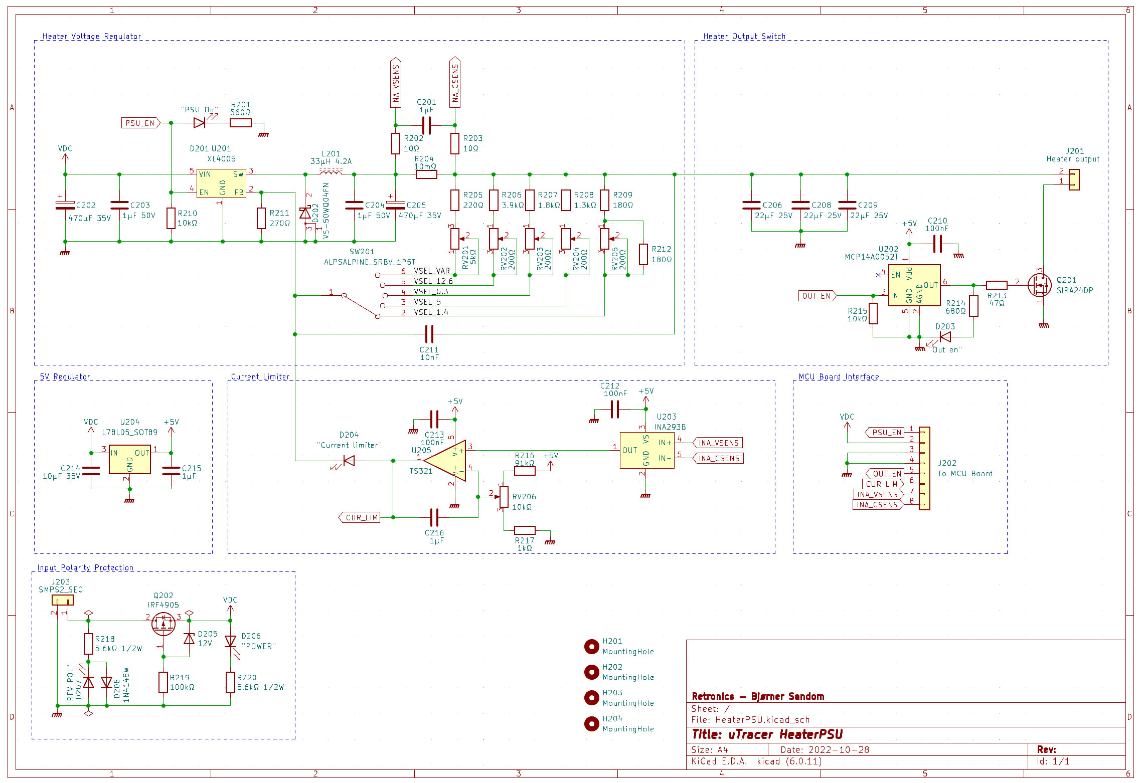
The circuit is powered by its own 19.5V/>3A laptop adapter, to ensure sufficient current capability, and to keep the heater PSU galvanically separate from the µTracer, all the way until an interconnection between the cathode and one heater terminal on the front panel.
MOSFET Q202 and surrounding circuitry protects the device against reverse voltage. This technique is described in an earlier post.
In the voltage feedback circuit, a rotary switch connects different voltage dividers to enable fixed voltages of 1.5, 5, 6.3 and 12.6V, plus a potentiometer (RV201) for variable voltage adjustment in the range from 1.4 to 16V. Trimmer pots RV202-205 are for fine-tuning the fixed voltages.
A high-side shunt resistor (R204, 10mΩ) is used for both the current limit functionality, and to measure the current draw. The current shunt is placed inside the voltage feedback loop, so that any voltage loss over this resistor is compensated for by XL4005.
With a low-resistance, high side current shunt, there is need for a current sense amplifier. I chose an INA293B which is basically a differential amplifier with fixed gain, and wide common mode voltage range. These come with different gain options, and I selected a gain of 20. At max current draw of 2.5A, the voltage drop over the shunt is 25mV. The output of the INA293B is then 500mV. A comparator/integrator based on TS321 op amp, compares the voltage from INA293B with a reference voltage set by a 5V regulator and voltage divider R216, RV206 and R217. If the voltage from INA293B is higher that the set reference, this means that the current draw is higher than the selected current limit, and the TS321 output gradually increases towards 5V. This voltage is fed to the XL4005 feedback pin through an LED (in the same manner as in the standard buck regulator in precious post). C216 ensures that the TS321 doesn’t suddenly jump to 5V, as this would cause the XL4005 to shut down its output, which in turn would reduce the current draw to 0, and the current sense voltage to 0, and the output of TS321 would go back to 0. Then the XL4005 would suddenly turn on the output again, and the whole cycle would repeat, causing a chopped up output voltage.
Close to the heater output terminal, MOSFET Q201 turns the output voltage on and off, on signal from a microcontroller on the measurement board (which will be described in next post). Pin socket J202 interconnects the two boards.
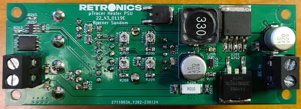
The finished PSU board, front and back:
PCB production files (Gerber) and KiCad design files are shared on this project’s GitHub repository.
Next post describes the measurement board.

Leave a comment