Retronics

Restoring, remodeling and creating electronic devices


µTracer (uTracer), part 3: Making a custom USB interface

As mentioned in the previous post, communication between µTracer and PC uses the obsolete RS232 interface, and unless your PC is old enough to have an RS232 port, you will need an RS232-to-USB-adapter.

During initial test and calibration, I used a USB adapter cable, but then came up with the idea to make a plug-in adapter that fits right into the µTracer board.


The “brain” of the µTracer is a PIC microcontroller that comes in a DIP40 package; a rare sight these days, but it has the necessary processing power and I/O to perform well in this application. The PIC communicates via 5V UART, and these signals are transformed to RS232 voltage levels by a separate IC (MAX232).

When programming basic microcontroller boards like the Arduino Pro Mini, UART-to-USB converters are often used for code upload and serial debugging. These converters are generally cheap, and can be bought from e.g. eBay. According to notes on the µTracer website, using such adapters isn’t always a success, but I gave it a try, and it worked flawlessly for me. Different adapters are based on various IC’s like CP2102 or PL2303, while the adapter I used was equipped with a FT232RL. Nonidentical adapters might behave differently.

Connecting the adapter was easy, since the µTracer actually has pin headers for Rx and Tx. Note that the MAX232 chip has to be disconnected for this to work. In the empty DIP16 socket, I found a suitable GND spot.

With these three wires in place, it was only to connect a USB cable and select the right COM port in µTracer setup, and voilà! It worked 🙂


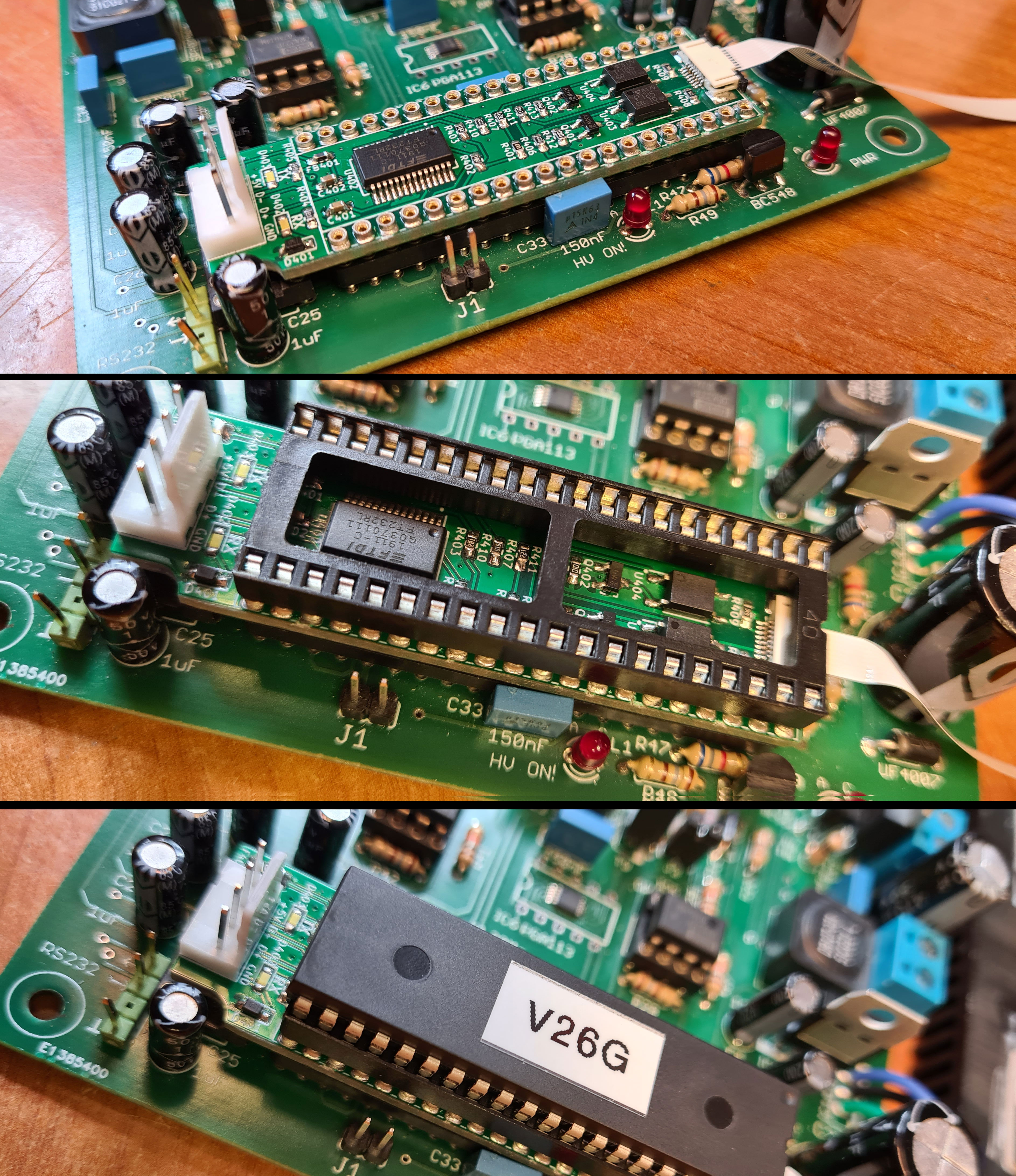
Next step was to create a more permanent interface based on the FT232RL. The DIP40 footprint of the PIC is large enough for a custom adapter board to fit between the IC socket and the PIC, and this socket gives access to the needed I/O pins on the PIC, in addition to 5V and GND.

I came up with this schematic:

Click for high resolution image.

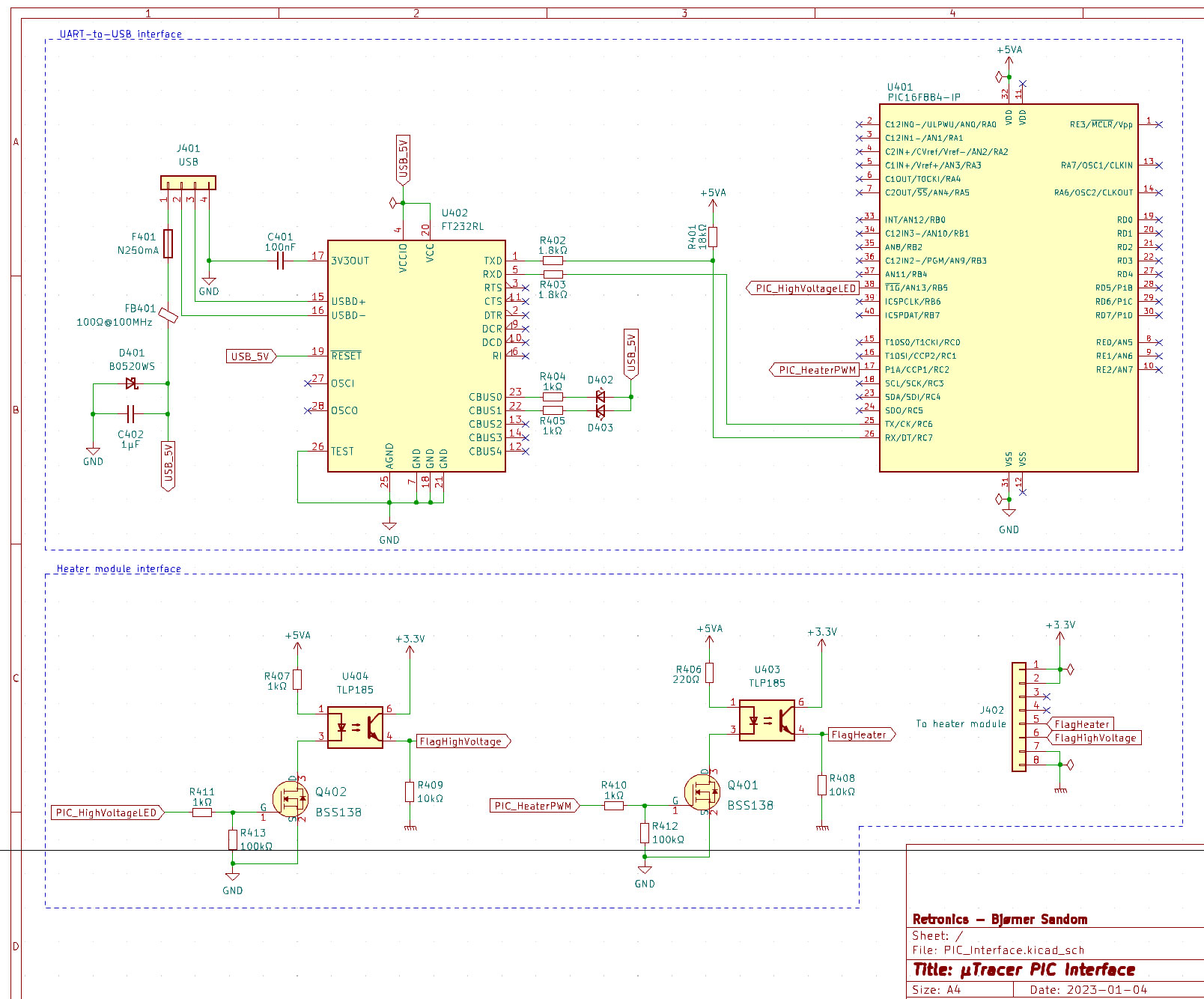
The schematic is segmented in two blocks: one for the USB interface and one with an optoisolated interface towards a custom designed heater module, which will be described in a later post. The USB interface circuit is mostly designed on basis from the FT232RL datasheet.

PCB design in KiCad. Production files (Gerber) and KiCad design files are shared on this project’s GitHub repository.

The downwards pointing pins on the 3D model are to be connected to the original DIP40 socket on the µTracer board. The small SMD components are placed to fit within another DIP40 socket (shown in grey), which will be the new base of the PIC.
The board with most components soldered in place. In front is something that looks like an IC socket, but these are the throughput pins that will provide connection from the DIP40 socket on the µTracer board, via the USB interface board, and to a new socket for the PIC. (The black plastic frame just holds the pins aligned when soldering them, and is removed later).
“PIC sandwich” with the different layers stacked on top of each other. The white 4-pin connector to the left of the interface board will lead to a USB B-connector at the back of the back of the enclosure, while the FFC cable to the right will be interconnected with a custom heater supply. This will be shown upcoming posts.

Next post is about testing the on-board heater supply.


6 responses to “µTracer (uTracer), part 3: Making a custom USB interface”

  1. Very cool! I’ve pretty much done the same thing using the same FT232RL-based adapter (without the custom PCB), however I’m finding that using this setup the order in which I connect things is important. If I connect the uTracer to the PC first, then to power, the inductors have an extra bit of ‘whine’ to them and the BD138 chip in the negative power supply tends to get very hot very quickly (I’ve already burned one out). If I connect the power first, then the PC, everything seems to work fine. Any ideas of what might be going on there? Seems like maybe the control signal to the negative supply boost converter is different when connecting the PC first, then power?

    Like

    1. It’s hard to say what can cause this behavior. What kind of power supply are you using for the µTracer? It should be galvanically isolated, i.e. with outputs not connected or referenced to mains earth, otherwise you will be connecting the µTracer to earth at two points; one via the PSU and one via the PC, which could cause ground loop issues.

      Like

    2. Also, I recommend connecting the FTDI adapter to the µTracer via resistors, to prevent the PIC from being partly powered up with current from the FT232. I used 1.8kΩ on the Tx and Rx lines.

      Like

  2. I’ve just been plugging my laptop power supply into the outlet. I’ll try using an isolation transformer and see if that helps. Good call on the TX/RX line resistors, I’ll try that. I’ve noticed the same thing–plugging the adapter into the board directly has enough juice that it powers up the uTracer LED. Thanks!

    Like

    1. Note that the 5V line from the FTDI adapter must not be connected to the µTracer. The only connections are TX and RX (via resistors) and GND.

      Like

  3. The resistors did the trick, thank you!

    Like

Leave a reply to havebra Cancel reply