
(Continued from DIY Plant light in an old bookshelf, Part 1: LED strips, dimmers and timer)
PCB design files (KiCad), fabrication files (Gerber), 3D models (.stl) and code for this project are shared on GitHub.
When germinating seeds, extra heat is often beneficial, and heating elements under the seed pots can stimulate root growth.
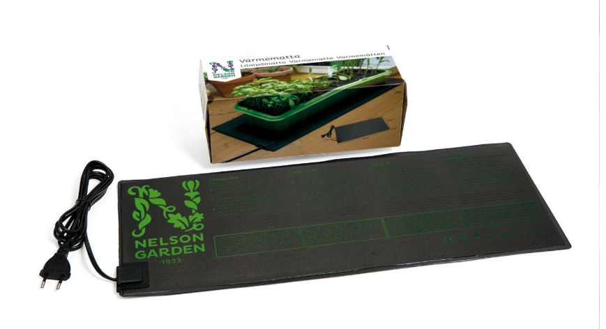
Heating pads, like this one from Nelson Garden, are readily available on the market, but I wanted a custom solution integrated in the plant shelves.
Finding suitable heating elements for shelf plates of 25×75 cm wasn’t easy. Floor heating foils come in different sizes and powers, but most alternatives seem underpowered for this use. 60W/m2 is a common value, and if I could find a heating foil covering the whole size of a shelf plate, this would deliver approximately 11 watts of heat; not sufficient to obtain the wanted temperature rise.
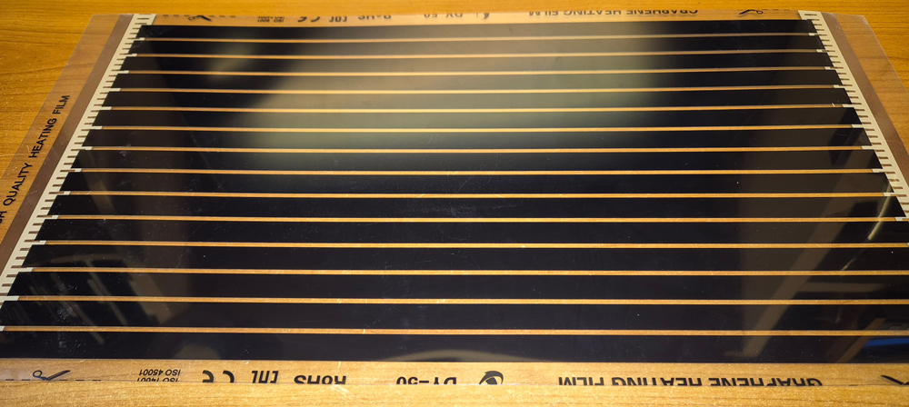
These heating foils from Aliexpress, measuring 50×25 cm and delivering 220W/m2 at 220V, would have to do. These are covering most of the area of the shelf plates (although a little wider foils would be better), and at 230V each such foil is delivering approx. 30W.
Thermostat
The temperature needs to be kept within a certain range. I designed a relatively simple thermostat for 230V, with adjustable temperature and triac output (click to expand):
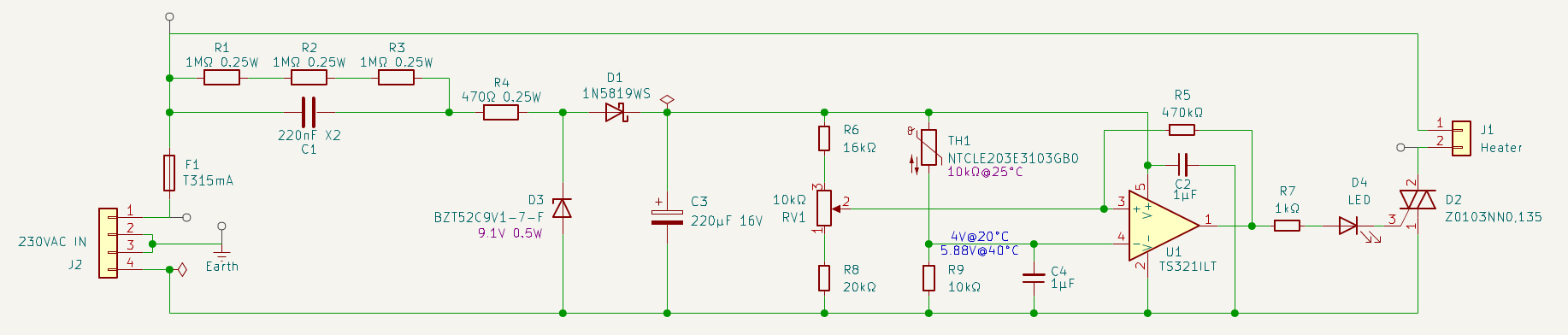
For cost-effectiveness and compact size, the circuit is transformerless, with voltage drop from 230V handled by a 220nF X2 safety capacitor (C1). A zener diode (D3) regulates the voltage to ca. 9V. A TS321ILT OP AMP works as a comparator, with negative input voltage coming from a voltage divider with a thermistor (TH1) and a fixed resistor (R9).

The positive input voltage of the comparator is set by a potentiometer (RV1), while R6 and R8 limits the adjustment range. I calculated resistance values to give the thermostat an adjustable range between approx. 20 and 40°C. A feedback resistor (R5) adds a few °C hysteresis, to prevent the thermostat from rapidly turning on and off. The output of the comparator drives a status LED and the triac gate.
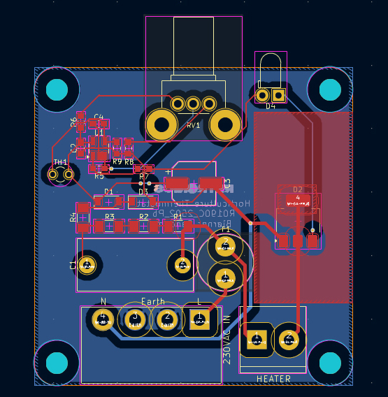
PCB design in KiCad. A small copper pour is sufficient to cool the triac. Mind that, due to the transformerless design, there are potentially lethal voltages everywhere in the circuit. Don’t touch components or wires while the board is connected to mains.

Left: An assembled thermostat, with NTC connected via thin wires, being covered with heat shrink tubing. Thermostat box models: ThermostatBox_Bottom.stl and ThermostatBox_Top.stl.
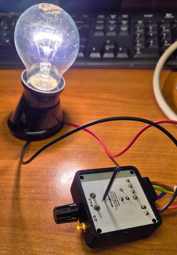
Below: Testing a thermostat with a 60W light bulb as dummy load (an earlier implementation of the PCB, with alternative NTC placement). With this load, the triac produced no noticeable heat.
Assembly
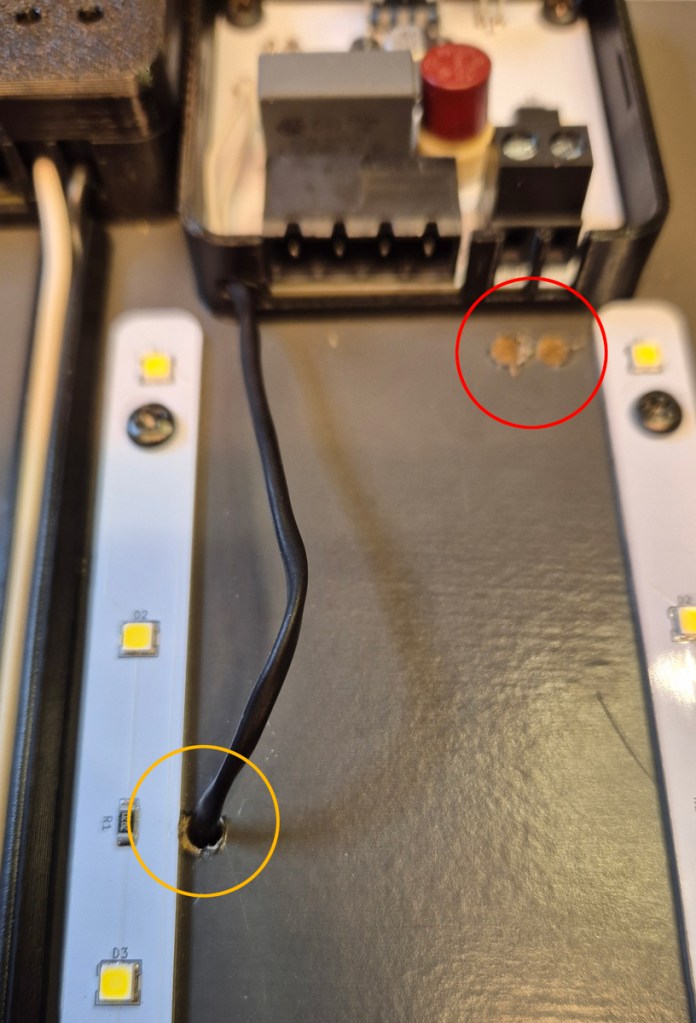
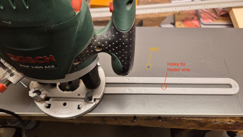
The thermostat box is placed on the bottom side of the shelf board, beside the LED dimmer, and secured with 3mm screws.
Three 3.5mm holes are drilled through the board: one for NTC (marked with yellow ring) and two for heater wires (red ring).
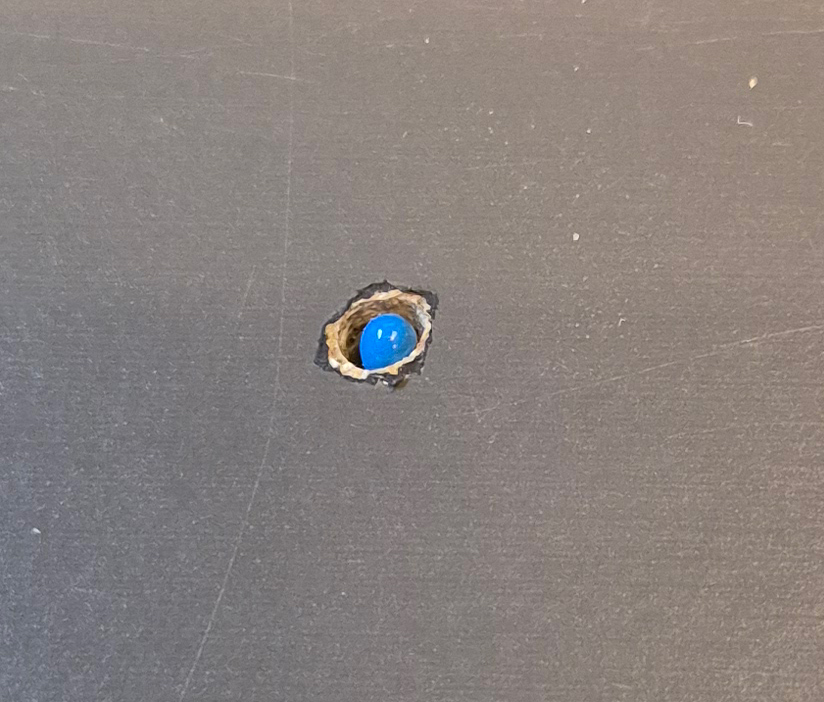
The NTC is placed level with the board surface on the other side.
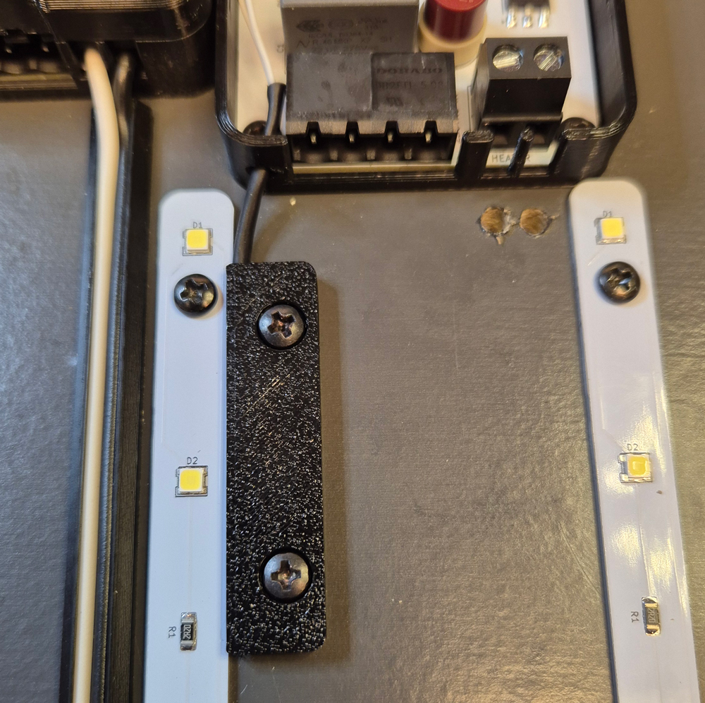
A 3D printed bracket (WireHolder_NTC.stl) keeps the NTC and wire in place.
Before mounting a heating foil on a shelf board, grooves for heater cables are made with a handheld router, 1/4″ flush trim bit, a 3D printed 12mm copy ring (model Copyring_Bosch_12mm.stl), and a custom router guide (RouterGuide_HeaterWire.stl).

The groove is made a little deeper than the thickness of the heater wire.
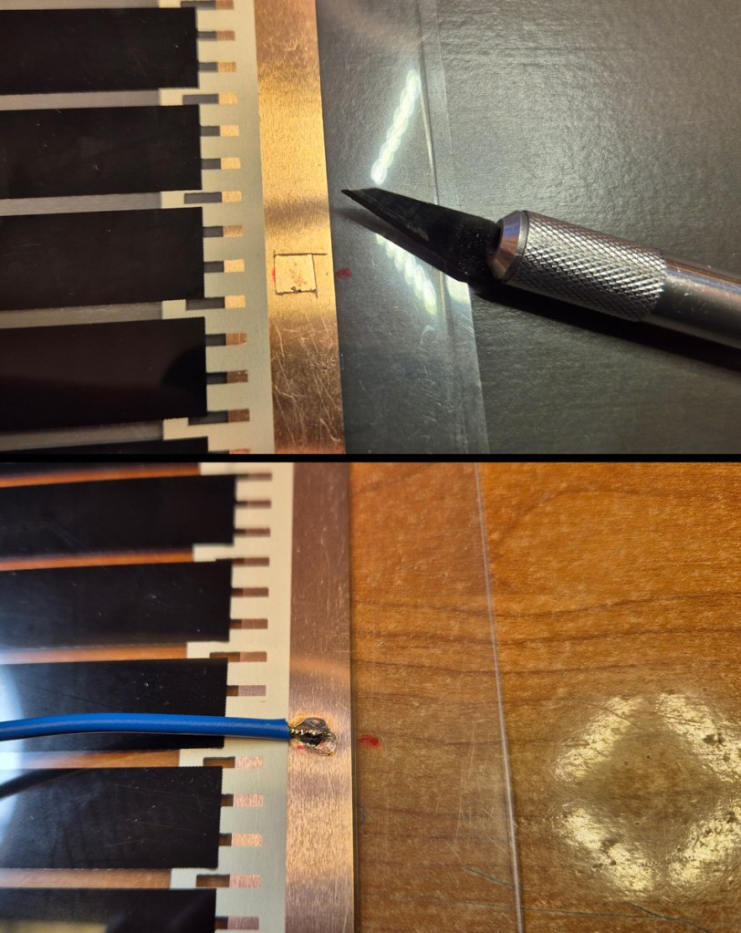
Draw marks on the heating foil where you want to solder the wires (must be aligned with the routed groove), then carefully cut out a small piece of the transparent plastic, using a sharp knife. Make sure not to damage the copper track. Then, solder wires to the tracks at left and right side of the foil.
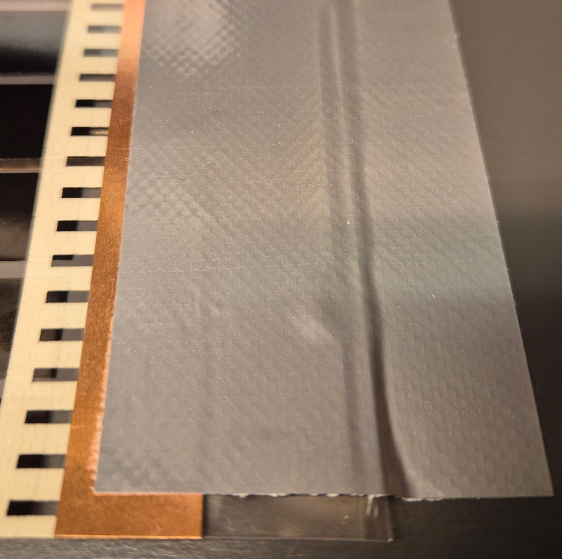
Thread the wires through the holes in the shelf plate, put the wires in the routed groove, and fasten the heating foil with tape.

On the opposite side of the shelf plate, cut the heater wires to exact length and attach them to the thermostat’s screw terminal.
Do also attach wire clips (WireClip.stl) for mains wire.

Mains connector: DORABO DB2EK-5.08-4P-BK-S. The reason for using a 4-pin connector, while only 3 pins are in use, is to eliminate the risk of confusing the 230 input to the thermostat and the 19V input to the LED dimmer, which has a 3-pin connector .
Before continuing, this is a good time to test the heating solution by connecting it to 230V mains and measuring the temperature of the heating foil surface. With the potentiometer, the temperature shall be adjustable between approx. 20 and 40°C, +/- a few °C.
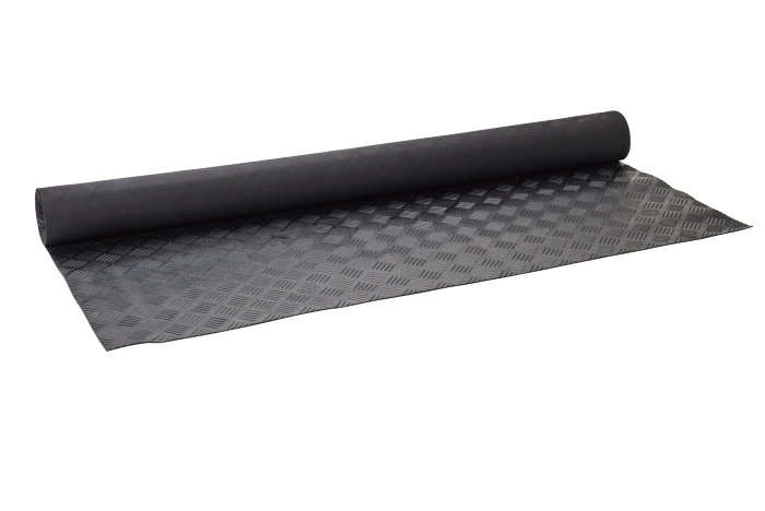
The heating foil needs protection against water splashes and physical damage. I chose a rubber mat which is commonly used for covering trailer beds, and cut it to pieces 1 cm smaller than the shelf plates, to give room for a frame along the edges.

The frame had to be split into pieces suitable for my 3D printer, and consists of ShelfEdge_1.stl, ShelfEdge_2.stl, ShelfEdge_3.stl and ShelfEdge_4.stl. You can stretch these models in your slicer application to fit your Plant Shelf size and printer size.

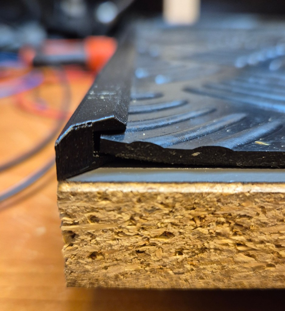
The plastic framing isn’t inherently waterproof, but it lifts the rubber mat a few millimeters along the edges, making it able to catch water splashes. Further waterproofing can be done by applying e.g. silicone sealant or Tec-7.
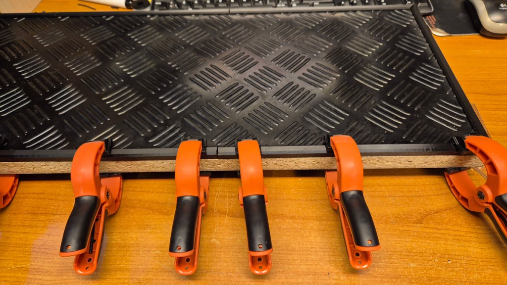
Repeat the process for as many shelf plates you want/need, and install them at desired heights in the shelf frame.
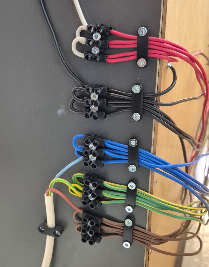
Wire connections on top of a shelf frame. Here, red and black is 19V supply to the LED dimmers, blue and brown is for mains voltage, and green/yellow is mains earth. Barrier terminal blocks are used for paralleling the wire groups, and wires run down the backside of the shelf, through holes in the back plate for connection to each shelf plate’s LED dimmers and thermostats.
Use strain reliefs (StrainRelief.stl and StrainRelief_2.stl).

Wiring, seen from the bottom side of a shelf plate.
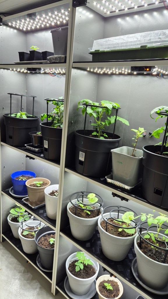
The complete solution, with seedlings in a mini greenhouse, tomatoes, chili and miscellaneous other plants:

Leave a comment