
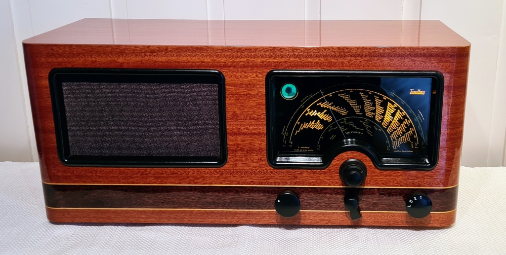
In the post WW2 years, there was a huge demand for broadcast receivers in Norway. Existing radio manufactures boosted their sales volumes, and several new manufacturing companies were established. One of the top selling models was Tandberg’s Sølvsuper 4, which was sold in the years 1946 to 1950, in a total number of about 70.000.
Visually, the SS4 wasn’t much different from it’s predecessors SS2 and SS3, except flame birch had been replaced by elm wood veneer. Perhaps it’s biggest advance on the inside was the new H165 loudspeaker, also designed and manufactured by Tandberg.

It may not look like much, but it sounds really well for a speaker of its time, and it was used in several radio models in the years to come, also by other radio manufacturers. Improved versions of the H165, with treble cone and/or larger magnet was made for the more expensive radios, plus some of the separate loudspeakers.
I’ve uploaded a scan of the SS4 schematic here.
This restoration process started with two Sølvsuper 4s, both in poor condition. The veneer was severely damaged on both cabinets, to such a degree that I found that the best solution was applying new veneer.


Cabinet refurbishment
Since this is a very common radio model, I didn’t feel obligated to restore the damaged cabinet it to it’s original appearance. There are lots of other SS4s that are well preserved. In lack of elm wood veneer, I decided to use mahogany instead; primarily because I think it looks nicer. Decoflex offers a variety of high quality, paper-backed veneers, which can be bought from e.g. Modulor.


Gluing the first stripe of veneer to the cabinet. I used ordinary wood glue. It’s important to have enough clamps, plus some bars and sheets of wood, to keep the veneer steadily in place while drying.


Excess veneer can be trimmed away with a sharp knife, but using a handheld router with a flush trim bit is faster.
The larger piece of veneer, which covers most of the front and sides of the cabinet, may be a struggle to keep in place while the glue dries, as it wants to straighten out to its previous shape, but with enough clamps, bars and sheets it is possible to make it tight around the cabinet bends.


Before the polishing process, it’s important to let the varnish fully harden, so give it at least a week before proceeding.


Openings for loudspeaker, dial glass and radio buttons, are cut out with a sharp knife.


Almost 80 years of finger dirt on the radio buttons. Water, soap and a toothbrush does the job, and the water turns disgustingly brown.


The speakers are in good condition. Speaker grill fabric is not. This needs to be replaced.
Checking and repairing the electronics
Before applying mains power, several measures are needed:
1. Initial inspection
Look for any clear signs of problems, like loose or deteriorated cables/wires, burnt or missing components.
On both mains transformers, the thermal protection fuses had opened, which indicated that there has been a significant overcurrent. Maybe that’s what killed the radios before they were tucked away, probably half a century ago. Just as likely, someone inadvertently ruined the radios when wanting to test if they still work, and suddenly exposing them to mains voltage after being unused for decades. If someone wants to sell an old radio, and they ask me whether they should check if they work, the answer is NO.
The thermal fuse is soldered with an alloy called Rose’s metal, which has a melting point around 95°C. If the transformer reaches that temperature, the fuse breaks open.
When soldering it together again, one cannot use ordinary solder, which has a much higher melting point. Wipe of any solder from the soldering tip, apply some flux to the soldering point, and reuse the Rose’s metal.
After a transformer has been heated up to such high temperature, it’s a good idea to check that it’s windings are still ok (not shorted together). In this case I had two radios with identical transformers, and therefore I could compare the resistance of each winding between the two. If there was a large discrepancy in resistance of the two primary windings, or e.g. the 6.3V secondary windings of each trafo, I’d suspect melted insulation. In this case, the two transformers had almost identical resistances.

The rubber insulation on the mains cable is crumbling to pieces. One can also see evidence of an earlier repair. Apparently the combined mains switch and volume potentiometer has been replaced. Since the earlier repair looks unprofessional, it’s a good idea to verify that the connections are correct.
The rubber cable of course needs to be replaced.

Just by looking at some of the capacitors, I know that they will have to be replaced. In the SS4, there are lots of paper/wax caps like the one shown here, and they all get leaky over the years. By leaky, I mean that they conduct DC current.
If your capacitance meter shows much higher capacitance than nominal for a given capacitor, there is a good chance that it is leaky. The DC leakage causes the charge time of the capacitor to increase, and the meter is fooled to believe that the capacitance is much higher than it really is. Here is a 10nF cap, measuring almost 3 times the nominal value.

On one radio, the mixer tube is missing, and I don’t know the state of the other tubes, but from the two radios combined there is a good chance that I’ll get a full set of working tubes, expect the 6U5 magic eye. These have a relatively short lifespan, and there’s a good chance that the radios have been used without them. One radio came with a 6U5 (left), but grey area in front is quite dark, and I don’t expect the green light to be more than barely visible when I power it up. On the other radio, there was an other type of magic eye (right) with octal socket. The labeling had flaked off, so I’m unable to identify it. It doesn’t matter, because it looks burnt out anyway.

I also notice that the socket for the EL33 feels quite loose. The sockets used in this radio appear to be of the cheapest kind. Maybe I can tighten them and establish stable connection, but it’s also possible that some of them need to be replaced.
If you’re lucky, you’ve got a SS4 with better octal sockets than the one shown here.
2. Eliminating causes of overcurrent
Since the power transformer’s thermal fuses had opened, it’s obvious that the radio has drawn a significant overcurrent. It might be due to a direct short somewhere, but the two most likely causes are leaky capacitors:
2.1 Leaky coupling capacitors

Under normal conditions, there is 0 volts DC on the EL33’s control grid, which makes it a negative 5.7V with respect to the cathode. If C30 gets leaky, the control grid receives a positive voltage, and causes the EL33 to draw more current. If the control grid reaches the same voltage as the cathode, the EL33 will draw more than 100mA (if the PSU can deliver it), about twice the recommended max current for this tube. This may overheat and destroy the tube, the output transformer, the rectifier tube or the mains transformer, unless some safety feature kicks in. That’s what the thermal fuse on the mains transformer is there for.

Here, I’m measuring leakage of this cap, with a homemade leakage tester. At 350V, the leakage current is 20µA. It may not sound like much, but 20µA flowing through a 500kΩ resistor (R17 in the schematic above) will cause a voltage of 10V. In real circumstances, the voltage over C30 will be 85V, and the leakage current proportionally lower, but still enough to completely offset the working point of the EL33.
The moral is: Always check coupling caps in the output stage before turning on the radio you’re repairing. Replace the caps if there is even the smallest sign of leakage. Modern film caps like polyester or polypropylene are good replacements.
2.2 Leaky electrolytic reservoir/filter capacitors
When being unused for a long time, the dielectric layer or electrolytic caps gradually deteriorate due to chemical reactions. An old radio like the Sølvsuper 4 may not have been powered on for half a century, and there may be very little left of the insulating aluminium oxide layer inside them. If suddenly exposed to their rated voltages, the leakage current may be severe, and potentially destructive for the rectifier tube and the power transformer. If you’ve got a variac, you may start from a low voltage and then gradually increasing while carefully monitoring the current draw. I prefer to disconnect the reservoir/filter caps and measure their capacitance, dissipation factor and leakage current, and if necessary try to reform them.


From the other radio (the parts radio), I scavenged a dual cap of the same kind, but in much better condition. Capacitance values are slightly above nominal values, and the dissipation factor is low, so these seem to be good.

I also tested the cap for leakage. Here, I’ve soldered a wire between the two capacitor segments to connect them together. Initially, there were a few mA DC current, but this decreased to about 100µA during an hour of reforming. This is very good for an 80 years old cap.

With the coupling cap replaced and the reservoir cap confirmed OK, the two most common causes of overcurrent were eliminated. For both radios, leaky coupling caps are the most probable causes of death.
3. Checking the power supply
One common failure on radios from this era is the power switch. Quite often the radios won’t turn on at all, and occasionally they won’t turn off. One easy way of checking the power switch without powering up the radio, is to measure the input resistance over the mains plug. When the switch is off, the ohmmeter shall indicate open circuit, and when the switch is on, it shall show the input resistance of the mains transformer. For a radio of this size, I’m expecting somewhere around 50Ω.

In this case, there was an open circuit, regardless of whether the power switch was on or off. The primary winding of the mains transformer was already measured and found good, and the mains cable was replaced, leaving the power switch as the primary suspect.

On SS4, the power switch and volume potentiometer are integrated in one unit. Filling the unit with WD-40 (or other sprays) will not do any good. You have to open it up to check and clean it properly. Sometimes the switch mechanism is broken, while in this case, the contacts are just dirty and corroded. I cleaned them with isopropyl alcohol and cotton swabs.
A little bit of lubricant may be good. I used EML Contact Cleaner/Lubricant from Electrolube.

This is a good time to also clean the volume potentiometer. Cleaning with isopropyl alcohol and cotton swabs, and leaving the carbon track dry, works fine in most cases. Don’t apply any lubricant to the carbon track, unless its specially designed for this purpose. DeoxIT Faderlube F5 has a good reputation, but I haven’t tried it myself.
Test both the switch and the potentiometer with a multimeter to verify stable contact before reassembling the unit.

After cleaning, the power switch behaves appropriately.


Rectifier tubes can also be damaged by overcurrent, so it’s time to test them. Visually, one doesn’t seem too bad, but one looks suspiciously dark.
To test a rectifier, while the state of the rest of the radio is uncertain, I left all other tubes still disconnected, and used a dummy load instead; in this case a 5.6kΩ power resistor. Due to the schematic, we can expect 280VDC on the rectifier, and a 5.6kΩ resistor would draw 50mA, which is close expected current draw of the radio.

The voltage is measured over the reservoir cap, which is directly connected to the rectifier’s output. In parallell with this cap is a 5.6kΩ resistor.
As we can see, the rectifier under test here delivers significantly lower output than expected. I’m not going to use this one.

Under same conditions, the other rectifier tube delivers a much higher output. I’m keeping this one, while the other must be considered used up.

At 230V this corresponds to 260mA. The fuse needs to handle a little more than than, so I used T400mA.
4. The audio amplifier
With the power supply confirmed OK, it’s time to insert the EF39 and EL33 audio tubes, and put them to the test.


This cap may not look to bad, but it’s actually suffering from a direct short.
C25, the electrolytic cap bypassing the cathode resistor of EF39, had dried out and was reduced from 25 to 4µF. Nothing to do about that, except replacing it with a new one.
In this radio, also a few resistors needed to be replaced, since they had almost twice their nominal resistance value.
When powering up the amp, it’s a good idea to use a dim bulb tester on the mains input, and a dummy load on the speaker output (instead of an actual loudspeaker), to reduce the chance of ruining something. If the dim bulb tester shines brightly, then you know something is drawing excessive current. If the light is dim, it should be safe to move on to mains voltage. When fully powered up, it’s time to measure DC voltages. Specially interesting is the voltage over R19, the cathode bias resistor of the EL33. It’s a 150Ω resistor, and the schematic tells us that expected voltage over it is 5.7V. This indirectly tells us that the expected current flowing through the output tube is 5.7V / 150Ω = 38mA. It the voltage over R19 is way above that, the EL33 is drawing too much current, and you must check the circuitry again. If the voltage over R19 is much lower than 5.7V, or nothing at all, the tube might be worn out. Both eventualities might occur due to poor connections in the tube socket. Try wiggling the tube and clean the tube socket.
One way of testing the amp is to inject tone from a function generator to the radios Gram input, and watch the output with an oscilloscope. I prefer to listen to it, so I’m using an audio source like a Chromecast Audio on the Gram input, and on the output, I’m using a speaker that works well, but which I’m also willing to sacrifice in case something goes wrong. It’s a good feeling when the amp is powered on for the first time in probably half a century, and it sounds well 🙂

The only problem i noticed during audio test, was scraping and pops when rotating the tone control and channel selector. A good cleaning with isopropyl alcohol and cotton swabs, followed by a little contact cleaner/lubricant while rotating the switches back and forth, fixed that.
5. Testing/fixing the radio receiver
Time to insert the mixer/oscillator tube (ECH35) and the IF amplifier/detector (EBF32), and also to check surrounding components. I replaced all paper/wax capacitors, since they were leaky.

When powering up the radio, with a wire connected to the antenna input, the radio should at least pick up some noise and make it audible through the speaker. In this case, what I heard was silence.
There could be several reasons for that, but one place to start troubleshooting, is to check if the local oscillator is working, by connecting an oscilloscope to the anode of the triode part of ECH35. In this case, the oscillator worked fine at all three bands.


I could have tried to transplant a socket from the parts radio, but since it had sockets of the same poor quality, I replaced it for something better. These octal sockets from eBay are good: https://www.ebay.com/itm/174923377876
I also replaced the socket for the EL33, since it felt loose, and the EBF32, since the connection was unstable when I wiggled that tube, and cleaning the socket didn’t help.
Now, the radio was brought to life, and I could hear the demodulated 1kHz tone on the speaker output.
6. IF alignment
For this step, I’m keeping the function generator connected to g1 of ECH35, via a 50nF coupling capacitor. On the speaker output, I connected an 8Ω power resistor, instead of the loudspeaker.

To prevent the radio’s automatic gain control from interfering with the alignment procedure, I locked the AGC line at -2VDC, by connecting a homemade voltage source across C22.
The traditional way of IF alignment, which is also described in the service manual, is injecting an AM modulated tone to g1 of the mixer, and measure the output voltage on the speaker terminal, and then trimming the IF transformers until max output is reached.

A more precise way is to use visual alignment. Here, the function generator sweeps the output frequency between 455 and 475kHz, and the IF frequency of 465kHz is in center of the sweep.

I’ve connected the oscilloscope probe to the second diode (d2) of EBF32, and the scope is set to trigger on a TTL sync signal from the function generator.


After some more tuning, the IF filters were centered around 465kHz. I didn’t manage to get a perfect symmetry around center, but it’s way better than before.
7. RF alignment

For these steps, I’m injecting an AM modulated signal into the radio’s antenna connector. The lowest output signal setting on my function generator is 1mVpp, which is too much. Therefore I’m using a homemade step attenuator. This also has a built-in dummy antenna for impedance matching.

7.1 Oscillator alignment
For each band, the radio is tuned to the frequencies indicated in the service manual, the function generator is set to the same frequency, and the corresponding trimmer caps and inductors (on the board marked “Osc.” in the figure) are trimmed until the demodulated tone can be heard via the speaker, and then fine tuned for max output amplitude.
7.2 RF filter alignment
After the oscillator is tuned at all given frequencies, it’s time to tune the RF filters at the same frequencies as in the previous step, but this time trimming the caps and inductors on the board marked “Gitt.” until max. output amplitude is reached.


Leave a comment