
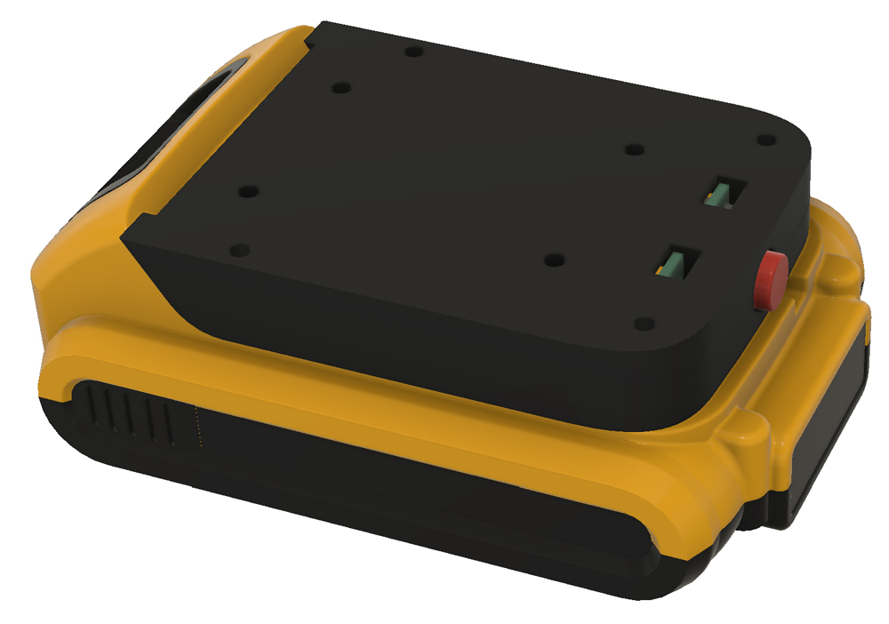
There are lots of light source that can be powered from DeWalt XR batteries (18/20V); both original and third party, ranging from torches to big and expensive lanterns which can illuminate a work site.
I wanted a compact and reasonably priced, omnidirectional lamp, bright enough to illuminate a room; primarily to use as a work light, but also to use as an emergency light during a power outage, and as a flashing warning light. Unable to find such lamp for sale, I decided to make one.
1. Battery connector
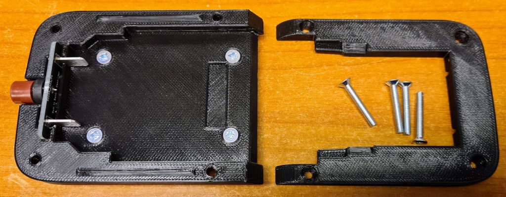
It’s likely that I’ll make other battery powered devices later, so I started by making a generic base and connector for DeWalt XR, shaped as a platform onto which different tools can be built.

3D modeling in Fusion 360. The battery connector consists of two printable parts, and a small PCB with connector blades that slide into the battery, plus a fuse (the red thing).
The platform has M3 screw holes for locking the pieces together, and for attaching different devices.
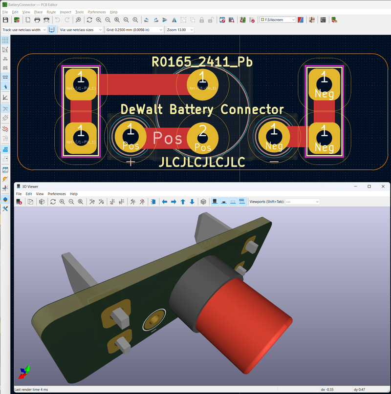
PCB design in KiCad.
The fuse is a Littelfuse 372, in this case T2A, with fuse holder.
The connector blades are Faston 62650-1.
2. LED drivers
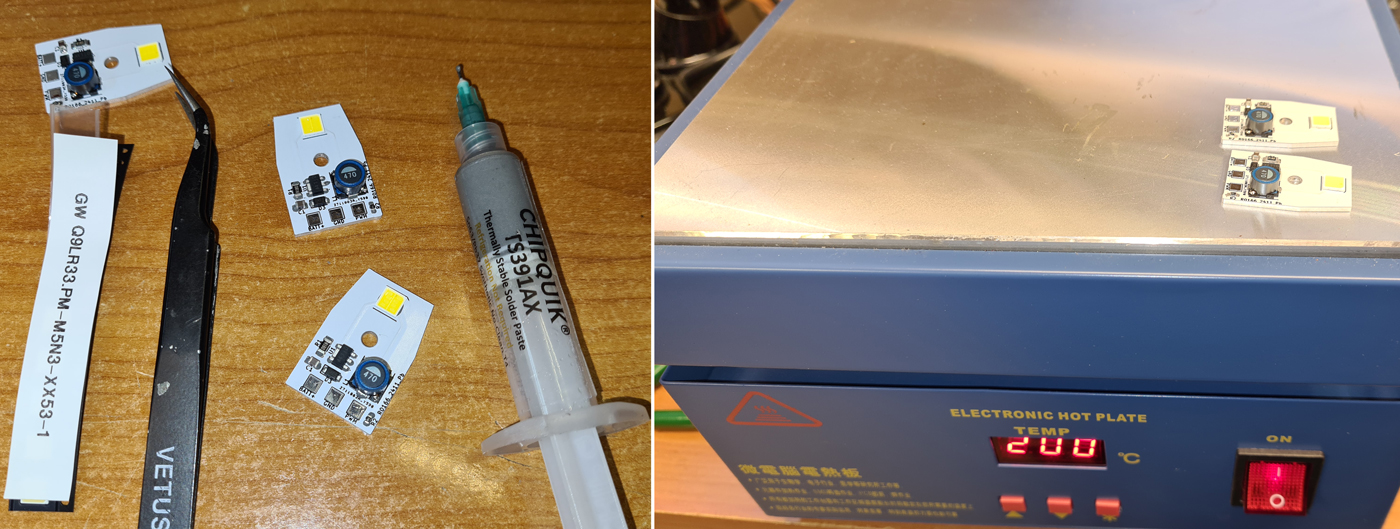
When making a small, battery powered device, it’s important to use high-efficiency LEDs; both to make the battery last as long as possible, and to avoid unnecessary heat. The ones I chose are Osram GW Q9LR33.PM-M5N3-XX53-1, which typically deliver 224 lumens per watt. Most LEDs you find on online marked places have less than half of this efficiency, so to deliver the same amount of light they would drain the battery twice as fast and radiate much more heat.
For making an omnidirectional light, several such LEDs are needed, and I decided to use five of these, placed in a pentagon shape. I also want to be able to control each LED independently, to use a single LED as a unidirectional light source, or to flash the LEDs in a circular pattern to use as a warning light. In addition, the brightness must be adjustable.
The XR battery delivers 18-20V, and the typical forward voltage of each LED is 5.5V, hence the voltage must be stepped down efficiently. The AL8861 LED driver is a good candidate for this. It is essentially a buck converter, with constant current output instead of constant voltage.


PCB design in KiCad.
Despite their high efficiency, the LEDs need a form of heat dissipation, and placing them on aluminium PCBs is simple and efficient. JLCPCB.com and several other PCB manufacturers offer aluminium PCBs for a reasonable price.

The LED driver boards will be mounted on a 3D printed part, to form a pentagon shape.
3. LED Controller
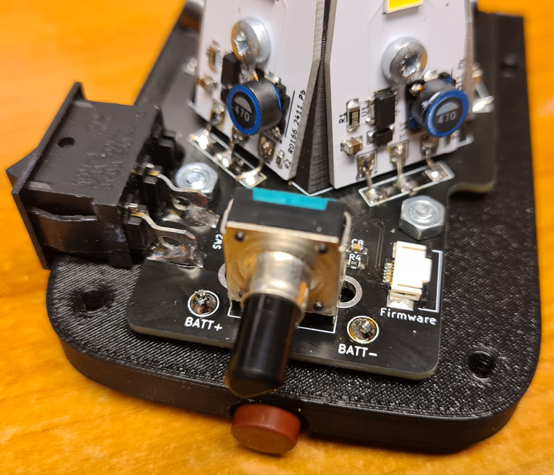
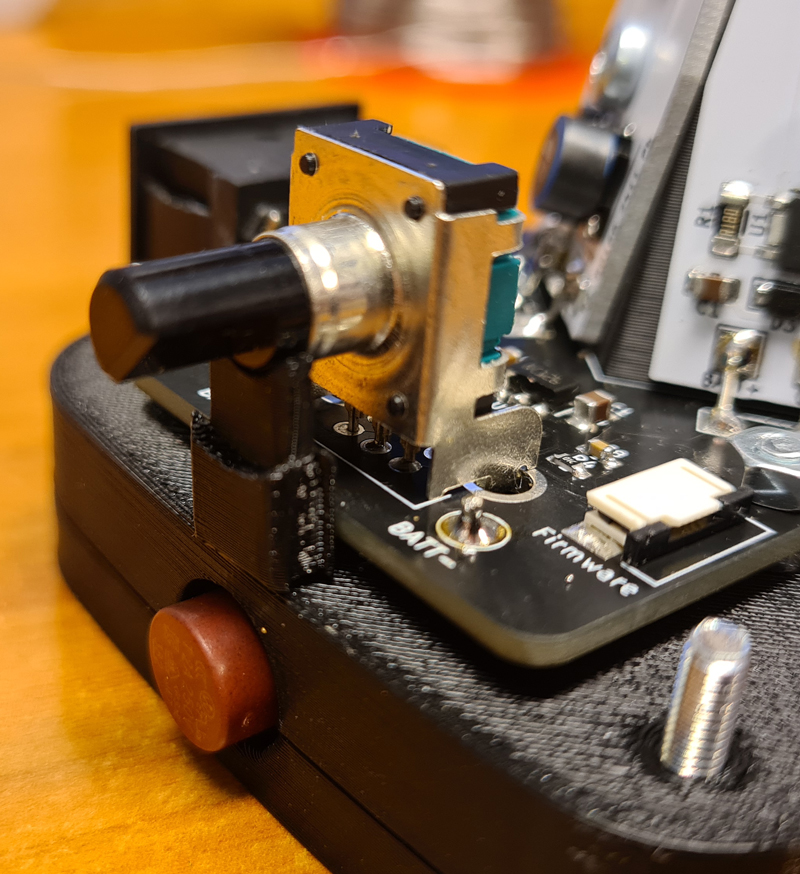
The LEDs will be controlled by an ATMEGA328P-AU microcontroller, with user interaction via a rotary encoder with push-switch.

Five PWM outputs from the MCU are used to control the LED drivers. The controller board also contains a 78L05 voltage regulator to provide 5V to the MCU, a 6-pin FFC connector for firmware upload, and a power switch.

Before soldering the ATMEGA328, you need to burn bootloader.

The tabs of the KCD1-A power switch need to be bent like this.

The aluminium LED driver boards are mounted to the 3D printed pentagon with M3 screws. Short wires connect the driver boards to the controller board.

Firmware is written in C/C++, using PlatformIO and the Arduino framework.
Code, PCB design files (KiCad), PCB production files (Gerber) and 3D models (.stl) are shared on Github.

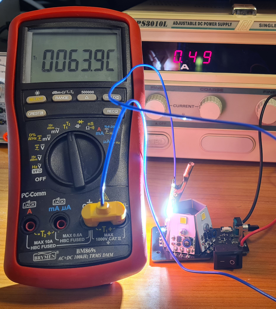
Temperature measurement with a single LED driven at the max setting of the driver board, i.e. 500mA. Running all five LEDs continuously at this current, inside a small compartment, would cause overheat. Therefore, the firmware reduces the PWM pulse width when de device is used in the omnidirectional work light mode.
4. Assembly

The battery adapter with sort wires through holes in the top; just long enough to reach the controller board.
M3 screws and nuts for mounting the controller board. The nuts in this picture act as spacers between battery adapter and controller PCB.
The controller board, mounted with another four M3 nuts. Battery wires are soldered like shown.
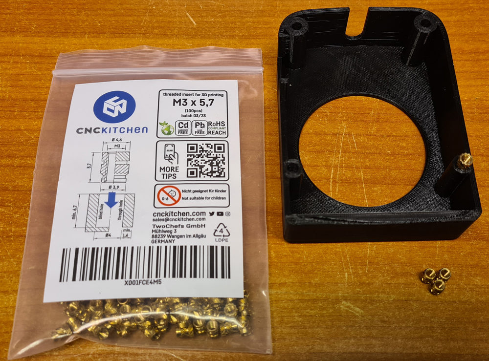
Four M3x5.7 threaded inserts are inserted into the lid. These can be bought from e.g. Prusa.

For insertion, I’m using a cheap soldering iron with a specialized solder tip, mounted on a Dremel drill press. The iron temperature is set slightly above the extruder temperature for the filament, in this case PETG.
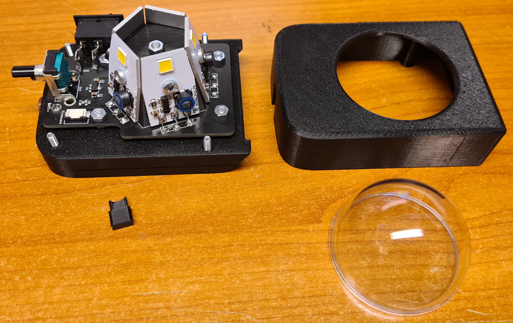
Put the 3D-printed encoder cover under the rotary encoder like this, before putting the lid in place and carefully tightening the screws.


Test run with a lab PSU. With 19V input voltage at the unit set in omnidirectional mode at max brightness, the current draw is 500mA. In theory, the 5Ah battery shall last 10 hours at this setting. After six years of use with various power tools, the capacity of my battery is lower, but it’s still a decent power pack.
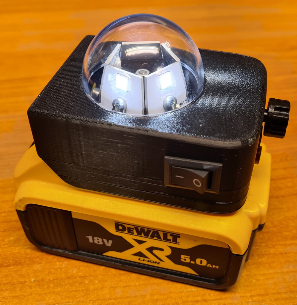
In use, with brightness at its lowest setting. Rotate the button to adjust brightness. Press the button to change between four modes:
- Single LED (unidirectional light).
- All five LEDs (omnidirectional light).
- Warning light. LEDs are flashing in a circular pattern.
- SOS morse code flasher.
Short demonstration video:
The phone camera is desperately working to avoid overexposure, and the light may sometimes appear flickering in the video, but not in real life. Also, I had to wear sunglasses when recording this video 😎

Leave a comment