
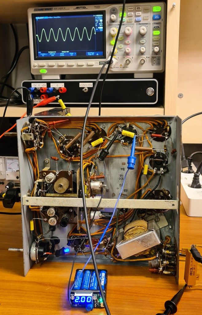
When aligning tube-based broadcast receivers, you often need to prevent the Automatic Gain Control (AGC) from interfering with the alignment process, and this is typically done by applying a certain DC voltage to the AGC line; negative with respect to ground.

2 volts batteries are uncommon, but one can use a lab PSU, provided that the PSU is isolated from mains GND on the secondary side. As an alternative, I decided to make a small, battery powered voltage supply, adjustable in the range 0.8 to 10V, and with integrated voltmeter.
Eight AAA batteries in series serve as power source. The circuit is based on LDO regulator TLV76601, which can deliver up to 500mA (more than enough for this purpose), and which has a low quiescent current of 50µA.

The voltmeter is a 3-digit 0.28″ panel meter, which can be bought from e.g. eBay.
There are two DPDT switches:
- SW1 A/B operates as power switch, which also disconnects the output terminal when power is turned off, to ensure that the radio’s AGC line isn’t affected when the AGC Disabler is off.
- SW2 A/B turns the LED voltmeter on/off. This has a current draw of about 10mA, so you only want the meter to be on when adjusting the voltage. The measurement input line also has a small current draw; that’s why the both VCC and M lines are switched by the DPDT.
Apart from that, there is a fuse and diode on the input from the battery (overcurrent and reverse voltage protection), and a LED to show when power is on.


How about if the radio receives a strong signal and tries to pull the AGC voltage beyond what’s set by the AGC Disabler? To find out, I used this test setup:

The AGC Disabler was set at 2.05V. The Lab PSU set at 10V and connected to the AGC Disabler and a voltmeter, via a 100kΩ resistor.
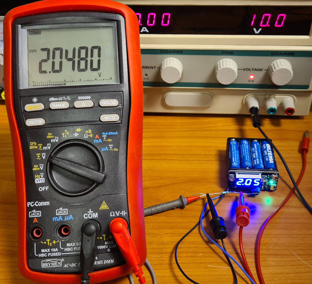
With PSU disconnected: measured voltage is 2.0480V.
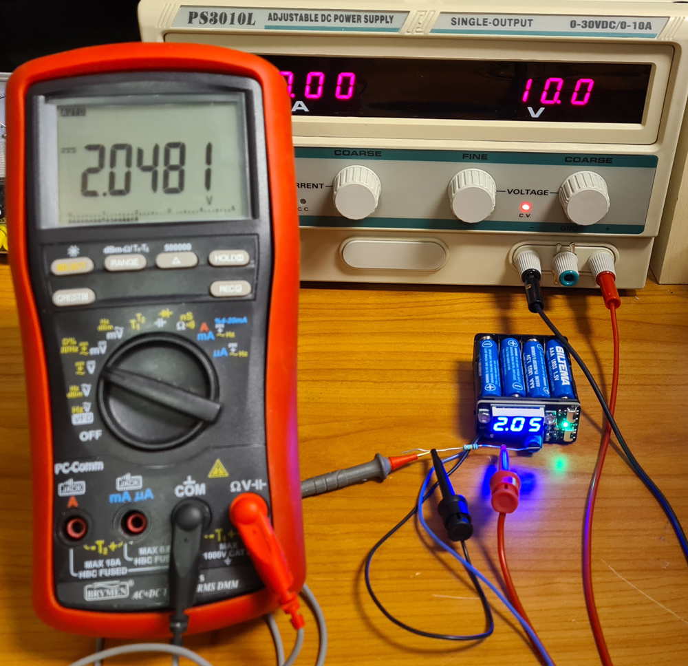
With PSU connected: measured voltage is 2.0481V, i.e. hardly any difference at all. This means that the AGC disabler clamps the voltage at set value. In reality, the AGC voltage source (detector circuit) on most vacuum tube radios has a much higher output resistance than 100kΩ, further reducing the impact. In the Sølvsuper 4 example, this resistance is 2MΩ.
If the polarity of the Lab PSU is reversed, it has no impact at all on the AGC Disabler voltage.

Leave a comment