
Got myself a nice TV for 50 NOK (USD 4.50), with only one problem: it was completely dead. No sound and no flashing of the status LED or backlight. These are signs that there must be a problem with the PSU board, which in this case is labeled BN44-00932C.

Silkscreen labels on the board suggest that the same PCB is used for several different TV models, both 55″ and 65″.
Unfortunately, I was unable to find schematic or service manual for the model numbers of the TV and PSU. Some PSU errors are, however, easy to locate and solve, and some of the first things to look for are swollen/bulging electrolytic capacitors, or burnt semiconductors or resistors, and of course broken fuses.

With the reservoir cap confirmed OK, I soldered it back in place, and continued looking for shorts in nearby components. Two switching transistors type KF7N50 were shorted (marked with red circle on the top right of the picture above). MOSFETs of the same type couldn’t be found at component suppliers like Mouser og Digikey, so I had to find some other with equal or better specs. A good place to look for substitutes is alltransistors.com, which uses key parameters like polarity, package, RDS, VDS, VGS, ID etc. to find relevant alternatives. The site came up with several suggestions, but none of them could be found where I usually buy components, nor in my own stock.
The Mouser and Digikey web shops do have good parametric search engines. I used Mouser this time, and from the KF7N50 datasheet, I used the following parameters: TO-220FP (full-pack), single N-channel, VDS >= 500V, VGS >= 30V, QG <= 16nC.

From this search, I found that SIHA6N80AE-GE3 looked like a good candidate. Before ordering, I also compared the datasheet drawings to verify that the pinouts were the same. The KF7N50 has a rated ID of 7A, while the replacement is limited to 5A drain current. On this PSU board, the transistors will not be subject to such high continuous drain current anyway, som I’m confident that they will not break down due to overcurrent.

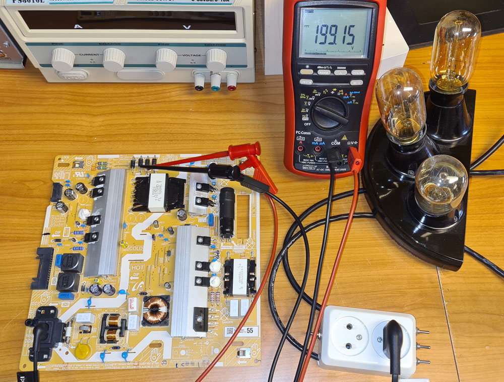
Transistors replaced. Time to test if the PSU board works now. For safety, I always connect the mains cable via a dim bulb tester. If a short circuit should occur, the light bulb will shine brightly, but the risk of components going up in smoke is significantly reduced.
This time, there were no signs of shorts, and the reservoir cap charged up to about 320V, which is what I expected for a cap which is charged from rectified mains voltage.
Sadly, all voltages on the secondary side of the PSU (after the isolation transformer) were still zero, so apparently there was no switching action.

Before continuing, I discharged the reservoir cap, using a DIY discharger pen, since I’m not very excited about inadvertently touching components or PCB tracks carrying 320V.

The next suspects were the components surrounding the switching transistors, and especially those in conjunction with the MOSFETs gates. No pulses on the gate -> no switching -> no output voltage.
Following the PCB tracks, I located a network of SMD resistors and diodes right underneath the switching transistors.
These are covered with something that appears to be silicone, but it can easily be scraped away with a fingernail, to access them with multimeter probes or soldering irons. The resistors and diodes inside the yellow rings were tested and found good. I did have to desolder some of them to get the right results with ohmmeter and diode test.

Next, I was looking for the component(s) responsible for delivering switching pulses to the MOSFETs. Following PCB tracks, I ended up at an IC labeled 6B20. This is an SMPS switching controller, and my next suspect. While googling for places to buy this IC, I found this SMPS example circuit incorporating 6B20: https://www.fujielectric.com/products/semiconductor/model/power_supply/technical/box/doc/pdf/RD_FA6B20N_180W_E.pdf

The 6B20 isn’t available from my usual component suppliers, so I ordered some from AliExpress.
After carefully scraping of the silicone, I applied flux on all the ICs pins, and then applied SMT Chip Removal Alloy, using a soldering iron. This alloy looks like solder, but has a much lower melting point, making it possible to get all solder points liquid at the same time by dragging the soldering iron along the pins, and then carefully lifting the IC from the board, using a tweezers. Any remaining alloy on the PCB must be removed (e.g. using solder wick), before the new IC is soldered in place. The IC removal can also be done with a hot air gun, but be careful not to overheat any nearby components.

With the new IC soldered in place, it’s time to test the PSU again.
Next: discharging the reservoir cap and other points on the PCB marked with “Discharge”, before reinstalling the PSU in the TV. Then comes the exciting moment when the TVs status LED and backlight flashes, you flip the TV up in vertical position to see the screen, and… it’s alive!

The described repair process worked for this particular TV and PSU board. Your TV may have different faults, but if you’ve got a TV with the same PSU and same symptoms (completely dead), this procedure may be worth checking out, since the same TVs/boards often fail in the same ways.

Leave a comment