
Warning! This project involves working with dangerously high voltages. Don’t try this if you don’t know how to work safely with electricity.
Recently, I bought a capacitor discharger from AliExpress, which looked promising on the web shop, but which turned out to be almost useless.


The device pretentiously labeled “Intellect capacitor discharger” is just 2 LEDs in antiparallel, in series with a 100kΩ resistor. The main problem with this, is that the high resistance makes the discharge processes too slow, even for fairly low capacitances, e.g. 100µF.
In my previous post, I gave this discharger a test run, and decided to make something better.
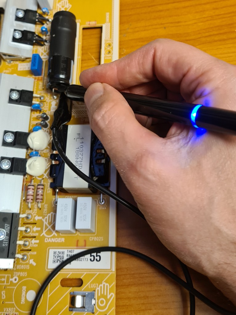
The first thing I made is a discharger pen, which works great for discharging e.g. the reservoir capacitors in vacuum tube radios or amps, up to a few hundred microfarads. I tested it up to 600 volts, which is the highest voltage I expect to need it for.
Though being almost 10 times as fast as the “Intellect capacitor discharger”, the discharger pen may be too slow for larger capacitors; say 1000µF or more.
Next project was to design something a little more powerful.
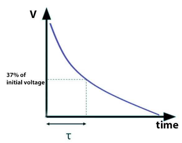
A drawback with discharging a capacitor through a resistor, is it works fast to begin with, and then gradually slower.
The time constant τ = RC. If the capacitor is 100µF and the resistor is 100kΩ, τ = 10 seconds. After 1 τ, the voltage is reduced to 37% of its initial value, but from there the process goes slower and slower.
An alternative way of discharging a capacitor, is using a constant current. Constant current sources can be created in different ways. I decided to use the voltage regulator IC LR8, which can handle up to 450V input and 20mA output.
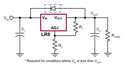
The LR8s typical use is as a voltage regulator, and it will adjust the Vout so that there is a constant 1.2 volts between Vout and ADJ. With a resistor voltage divider, we can set the desired output voltage.
(Image from datasheet).
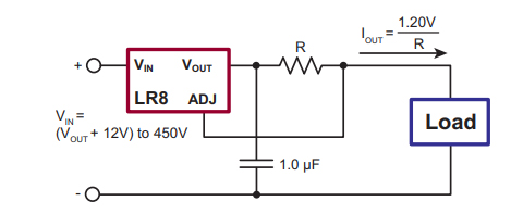
Since the LR8 keeps the voltage between Vout and ADJ at 1.2V, we can add a shunt resistor between these terminals, and now we’ve got a constant current source, where Iout=1.2V/Rshunt.
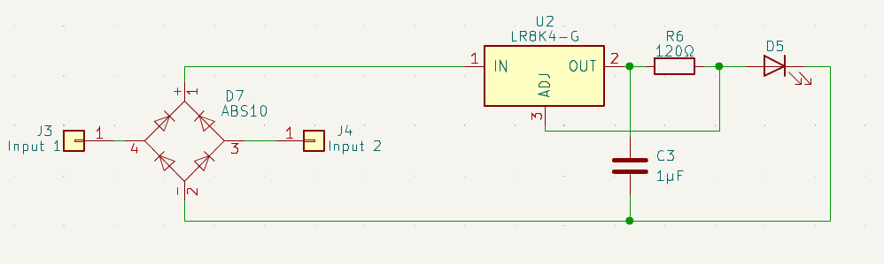
There is one significant limitation to this circuit: the LR8’s max input voltage is 450V. In some tube amps and radios, the voltage is likely to be higher than that. Therefore, I added a voltage limiter stage before the LR8.
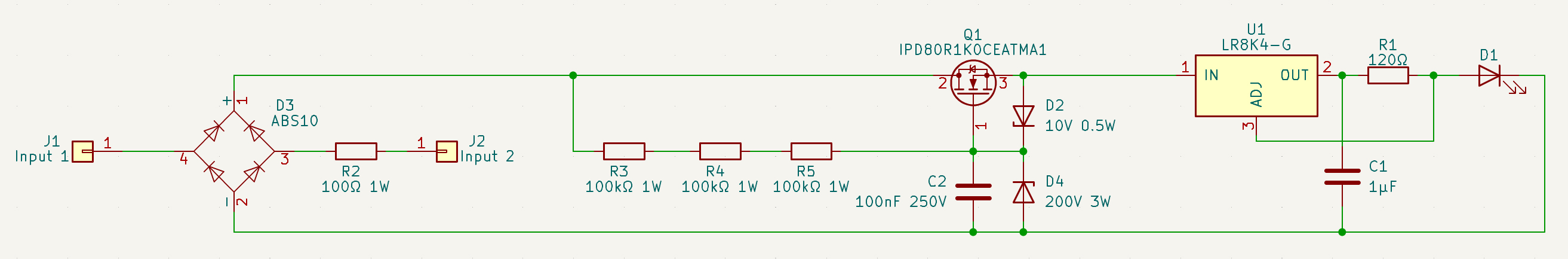
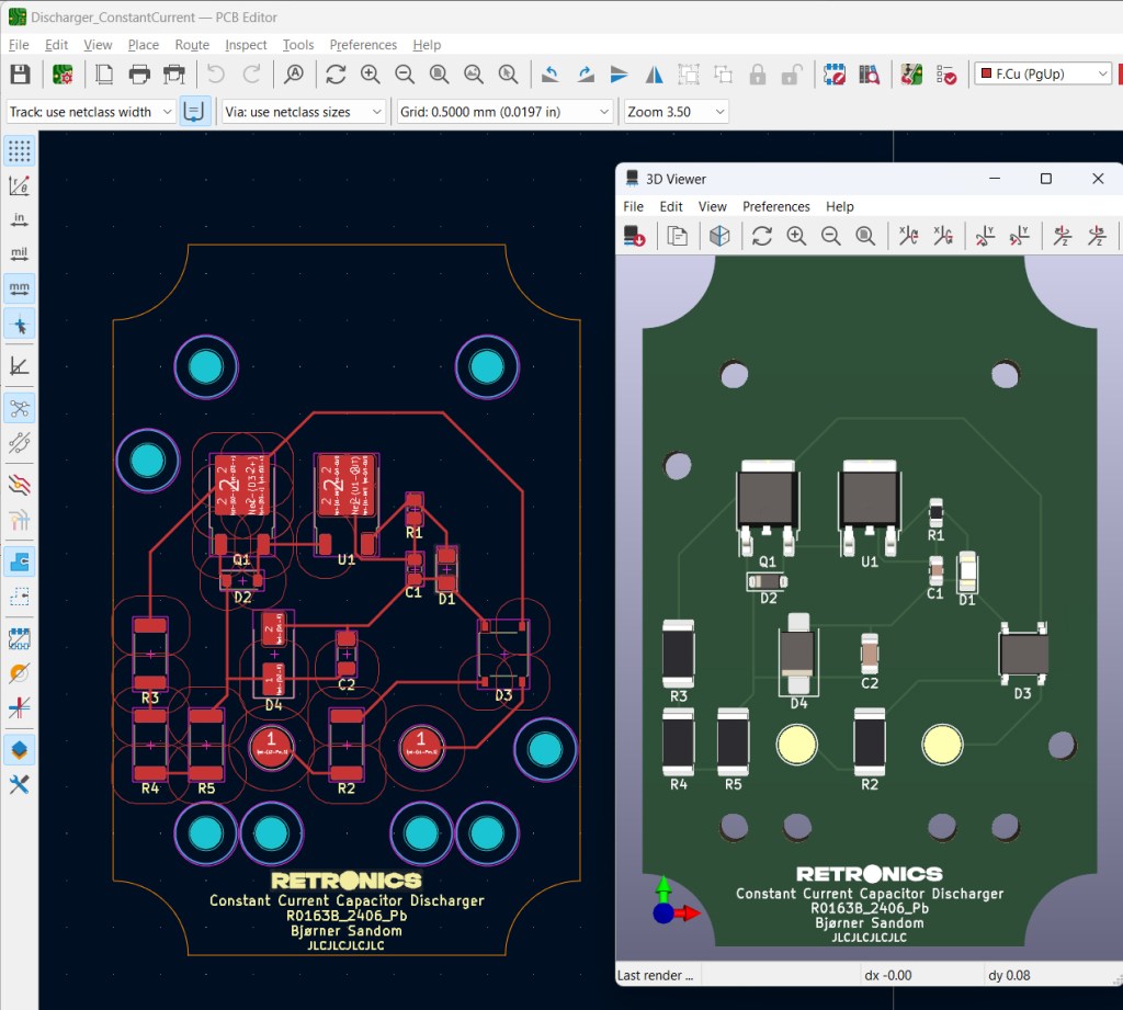
The LR8 comes in different packages, both THT and SMD, but SMD is preferred due to its capability to dissipate heat via the PCB. The tracks are laid out with proper spacing for the high voltages.
I got it manufactured on an aluminium board, since this provides much better heat transfer than the standard FR4. JLCPCB.com offers aluminium PCB manufacturing.
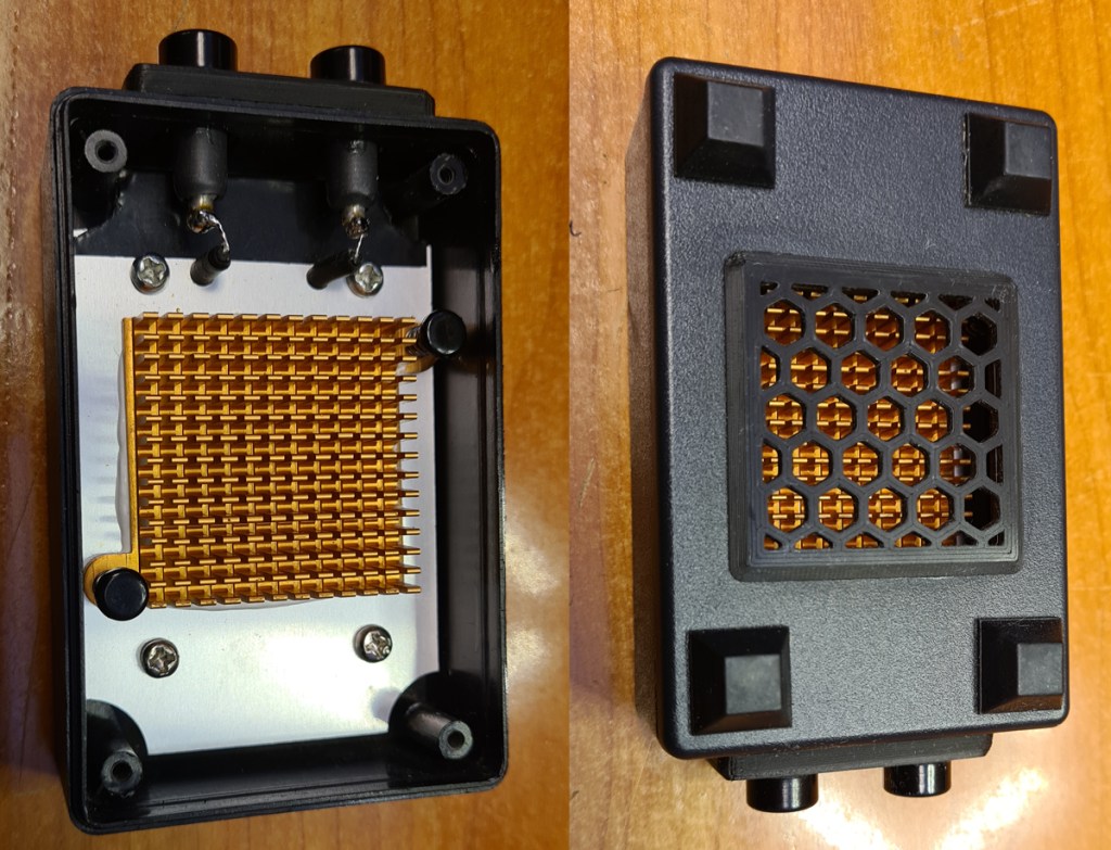
The board dimensions are selected for it to fit into the ABS box from the “Intellect capacitor discharger”.
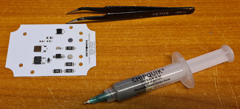
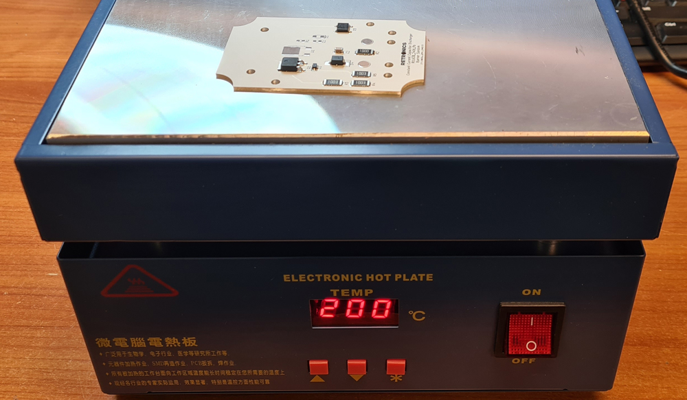
The heat transfer of the aluminium board makes it hard to solder the components with a soldering iron. Instead, i applied solder paste and used a hot plate.

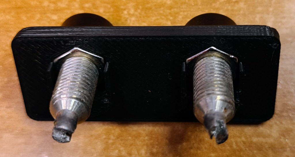
I also made an adapter plate for better banana jacks (BIL20), as the original holes were too large.

Test run with a homemade PSU. The discharger draws a constant current of 10mA over a broad voltage range.
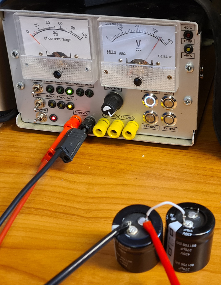
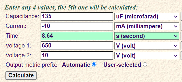
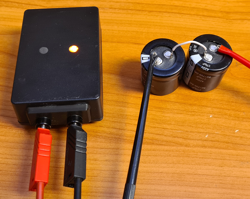
For higher voltage testing, I connected two 270µF capacitors in series, and charged them independently.
Several test were performed at around 650V, and with both polarities. Works like a charm, and there is no noticeable heat. The LED shines at a constant brightness during the whole discharge process. Discharge time was about 9 secs, and there was about 10V left when the LED went dark.
Discharge time for a certain capacitance and voltage can be calculated here. Enter current = -10mA.
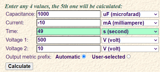
Let’s take an example of a 1000µF capacitor at 500V. That’s a big can, which you may find in a fairly large tube amp. Discharge time is 49s. You’ve got time to wait that long.
If the same capacitor was to be discharged by the tool I bought from AliExpress, where discharge is done through a 100kΩ resistor, the discharge time would be an estimated 5τ = 5*R*C=500 seconds. Life is too short for that.
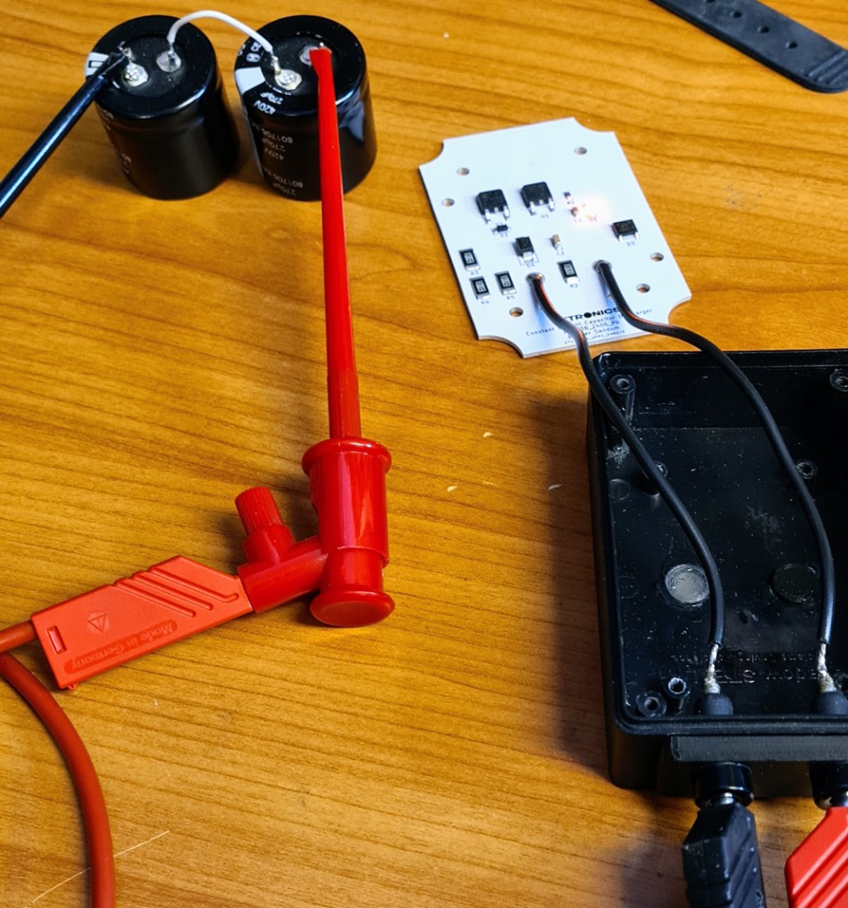
In use, discharging two 270µF caps (135µF in series), charged to about 650V.
Quick and easy for the typical caps you’ll find in tube radios/amps or switch mode power supplies.
If, however, you need to drain the insane 1F capacitors of your overdimensioned car stereo, this is not the tool you need.
Design files (KiCad), production files (Gerber) and 3D models (.stl) are shared on Github.

Leave a comment