
When you need an interface between a microcontroller’s UART ports and a PC, one of the FTDI serial adapters which can be bought from online marketplaces like eBay, may come in handy.

These usually come with USB mini connector, a jumper for selecting 3.3 or 5V logic, and a 6-pin 1/10″ (2.54mm) pin header for connection to the MCU.
FTDI is the manufacturer of the FT232 chips that these boards are based on.
Sometimes, however, when making small PCBs containing microcontrollers like the ATMEGA328P, a 6-pin 1/10″ pin header would be too large to fit on the board. Therefore, I designed an alternative FTDI adapter with a much smaller FFC connector with 0.5mm pitch.
The circuit is pretty much the same as on the aforementioned boards, with an FT232RL chip, LEDs for indicating traffic on Tx and Rx, and a voltage selector jumper. I’ve used USB micro and 6-pin FFC connectors.

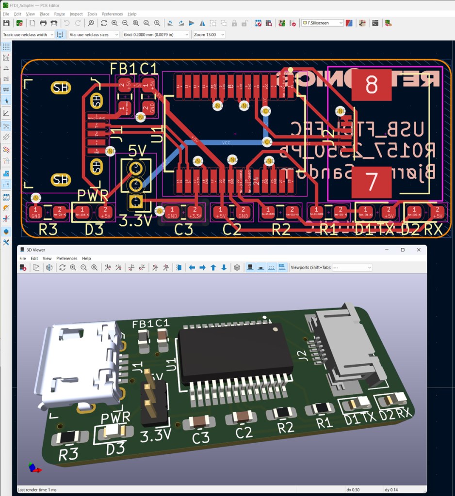
PCB design in KiCad. Cad- and production files (Gerber) are shared on GitHub.

Custom FTDI adapter (black) vs standard adapter board (red). A 6-wire 0.5mm pitch FFC wire is connected to the custom board.
When designing microcontroller boards which implement this interface, please make sure that the Rx pin of the FTDI connects to the Tx pin of the MCU, and vice versa.


Leave a comment