
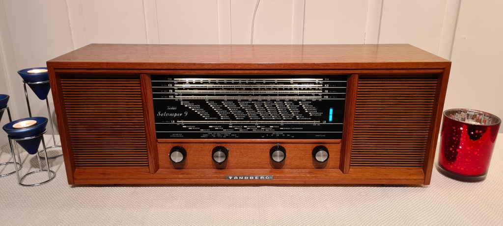
This is a pretty basic AM/FM receiver, manufactured from 1965-67, as table top models with either one or two integrated speakers, and as part of a radio/TV console. This was the last Tandberg radio with vacuum tube audio stage, and all variants of Sølvsuper 9, even the one with two speakers, had mono amplifiers based on a single EL84.
From a long patient queue of broken radios, I picked two SS9s, one with damaged cabinet and both suffering from earlier unskilled repair attempts. The goal was to make one well functioning radio, while the other would be sacrificed for parts. I’m not a seasoned radio repairman, but after some restoration projects, I’ve found some standard troubleshooting steps and procedures which usually lead to success. For beginners, I’ve documented the steps I went through to make this radio working:
1. Getting the service manual, or at least a schematic
With some web searches, there is a good chance that you will find a .pdf with the info you need. When it comes to Tandberg, someone has been kind enough to share an extensive collection of scanned service manuals, schematics and other info on this web page: http://tandberg.datagutten.net/. In case this page should disappear, I’m keeping a local copy of most of these files, and I’ve also shared the SS9 documentation here.
2: Visual inspection
Never try to power up the radio before going through a few basic steps! After opening the cabinet, a good start is to look for obvious faults like burnt or missing components, broken fuses, loose wires and cracked cable insulation.
In this case, both radios show evidence that they have stopped working as fuses broke due to excessive current draw, and that someone unqualified have tried to bring them back to life without fixing the root cause of the problem.

The power supply board consists of a glass fuse, bridge rectifier, reservoir/filter capacitors (a can with 3 electrolytics), two fusible resistors which drop the rectifier voltage to appropriate levels for different stages of the radio, while simultaneously working as low pass filters in collaboration with the filter caps, to significantly reduce ripple voltage.
On the mains transformer there is a thermal fuse made by roses metal (an alloy with low melting temperature), which will melt and break the circuit if the transformer is starting to overheat.


It’s obvious that the power supply needs to be fixed, and one or more causes of overcurrent has to be eliminated before connecting mains power.
3 Eliminating causes of overcurrent
Apart from direct shorts, there are two very common causes of overcurrent, destroying radios from this era:
3.1 Leaky coupling capacitor(s)
This will alter the grid bias voltage on audio output tube(s), which in turn causes the output tube(s) to draw excessive current.

In SS9, C81 works as a DC blocking capacitor between the anode of the audio amplifier triode of EABC80, and the control grid of EL84 output tube.
This is a Rifa Miniprint capacitor, and these always become leaky after some decades (they start conducting DC current).

There was never any doubt that this capacitor had to be replaced, but out of curiosity I tested how bad it actually is, using a homemade capacitor leakage tester. At 350V and room temperature, the leakage current is 45µA. It may not sound like much, but it’s enough to totally screw up the bias point of the output tube. In a worst case scenario, the tube’s current draw could ruin the EL84, output transformer and/or mains transformer, especially when someone has tampered with the fuses which are ment to protect the circuit.
This Rifa cap is rated for 400VDC, and at that voltage there should be no measurable current on this instrument. Always replace these caps before powering on a radio like this!
3.2 Shorted or leaky electrolytic capacitors in the power supply
If you’ve already tried powering on the radio, make sure the electrolytic caps are discharged before connecting capacitor testers or other sensitive instruments. The discharging should be done in a controlled manner, by connecting a power resistor of e.g. 1kΩ between the poles. Don’t try to short the poles.
In some cases, electrolytic capacitors may short spontaneously, often due to overvoltage. Shorts can easily be detected by a multimeter. If a capacitor is shorted, it needs to be replaced.
More commonly, electrolytic capacitors gradually become leaky. When you start working with an old radio, it may not have been powered up for several decades. This has given the dielectric made of aluminium oxide lots of time to deteriorate, allowing DC current to flow between the electrodes. This kind of leak usually can not be measured by a ohmmeter, due to the test instrument’s low voltage. A standard capacitor tester / capacitance meter will not detect de leak, but it may show way higher capacitance than what’s real, due to the way capacitance measurements are performed. To test the capacitors at their rated voltage, I’m using the aforementioned leakage tester. How much leakage is allowable? This chart gives some directions:

If you’ve got a 68µF capacitor rated for 400V, a leakage current of up to about 1mA (measured when applying its rated voltage), is acceptable.
How about if the leakage current is higher than that? This doesn’t necessarily mean that the capacitor needs to be replaced. Often, the dielectric layer can be gradually be regained by applying a controlled DC voltage and current over time, in a process called reforming.
In SS9, the PSU smoothing cap is a can with 3 capacitors, with nominal capacitances of 32µF + 32µF + 16µF, and voltage rating of 350V.

To speed up the test and reforming process, I soldered a wire across the 3 capacitor terminals, thereby connecting them in parallell.
The first seconds, there will be a quite substantial current to charge the capacitors.
After the initial charging, the leakage current was several milliamps, even at much lover voltage than the max rating. This is DC leakage due to dielectric deterioration.

After slowly increasing the voltage up to about 350V, and leaving it on for an hour or so, the total leakage current of the 3 paralleled caps was about 900µA. The chart above doesn’t show capacitances 16 and 32µF @350V, but interpolating the closest values gives an acceptable leakage of around 600µA + 600µA + 400µA = 1.4mA. In other words: there is no leakage problem.
If I had left the voltage on for several hours, the reforming process would continue, and the leakage would decrease further.
4. Checking the power supply
4.1 Smoothing- and filter caps
After reforming and discharging the capacitor can, it’s time to check its other properties, using an LCR meter.

At 120Hz test frequency, the capacitors measured only 23+23+14µF, significantly less than the nominal 32+32+16µF. Does this mean that the capacitor has partly dried out and lost some of its initial capacitance? It ain’t necessarily so.
The LCR meter also shows an ESR of 2.8Ω. ESR is an unwanted resistance in series with the capacitance, and most of the resistance is in the electrolytic material. Lower ESR is better. There are lots of ESR charts online, and they show very different values for what’s considered good or bad. 2.8Ω for a cap with this capacitance and voltage rating, is regarded as good in some charts, and bad in others. The measured ESR also varies a lot with test frequency. At 10kHz an ESR of 190mΩ is measured.


Datasheets for electrolytic caps usually don’t mention ESR, but instead Dissipation Factor.
If we applied AC voltage to an ideal capacitor, there would be a 90° phase shift between voltage and current. Real capacitors are not ideal, and the angle is less than 90°, due to ESR. The discrepancy from the ideal angle is called loss angle, with symbol δ. Dissipation Factor = tan δ = ESR/|Xc|. At 120Hz, the measured DF = 0.049.

I’m unable to find datasheet for the old TCC (Telegraph Condenser Company) capacitor from Sølvsuper 9, but let’s instead compare the measured values to a modern electrolytic cap, e.g. a Panasonic EEUEE2V330 (33µF, 350V). As we can see, max. tan δ for a good capacitor of this type is 0.2. The measured Dissipation Factor (tan δ) of the old TCC is about 1/4 of that. This is looking promising.

The datasheet also specifies a max leakage current of 0.06 CV + 10µA. For a 33µF 350V cap, this is (33*10-6*350*0.06)+10*10-6=703µA. When all three caps of the TCC can were connected in parallell, I measured a leakage current of about 900µA. Not bad at all.
The low values for leakage an dissipation suggest that the old capacitors are still good, even though measured capacitance is almost 30% lower than nominal. The capacitances may have been almost this low ever since the cap was new. I therefore decided to try to use the old cap can as it is. If the capacitance is too low for this radio, there will be an audible hum.
4.2 Checking/replacing the bridge rectifier
On one of the radios, the selenium rectifier has been replaced with a silicone bridge, in a really bad way (as shown in one of the pics above). On the other radio, the original rectifier was still present, but since it had been subject to significant overcurrent, I expected it to be broken. Measuring its diodes with a multimeter quickly revealed that the rectifier was shorted, and needed to be replaced.

The rectifier housing plays an important role in keeping the PSU board attached to the chassis. Also, I want the radio to look authentic, and modern bridge rectifiers come with a different pinout, hence they wouldn’t fit nicely on the PCB.
A better way is to re-stuff the old casing with new diodes.

To the left, the original selenium diode plates are shown. We can also see blobs of metal which has probably melted during an overcurrent situation.
On the pic below, I’ve inserted 1N4007 diodes to form a rectifier bridge with the same pinout as marked on the case (- AC + AC -).


Re-stuffing the case with silicone diodes doesn’t make the rectifier as good as new; it actually makes it better than that, which is not solely a good thing. Selenium rectifiers do have a significant voltage drop even while they’re healthy, while the silicone rectifier voltage drop is much smaller. To compensate for this, a resistor is added in series with the rectifier. Based on experience with similar radios, I used a 68Ω 3W resistor.

Left: The modified PSU board. The track between rectifier and 510Ω resistor is cut, and a 68Ω resistor is attached.
Below: Rectifier and capacitor can on bottom side of the board.

Of course, I also inserted a fuse with correct value: T160mA.
4.3 Checking mains cable, power switch and primary side of mains transformer
Before powering on the radio, it is a good idea to perform a simple check of the mains circuitry by attaching a multimeter to the mains plug and measuring resistance. On a radio of this size, I’d expect somewhere between 30 and 50 Ω when the power switch is on, and open circuit (infinite resistance) when the switch is off.
If the resistance is much lower than expected, it may be due to a burnt transformer coil. A direct short may suggest a shorted or incorrectly connected mains cable (one never knows with a radio which shows evidence of previously failed repair attempts, like this one).

If infinitely high resistance is measured, there are several suspects:
- Broken thermal fuse on the mains transformer. Here, the thermal fuse is intact. This fuse is a wire of an alloy called roses metal, which has a melting point around 95°. If the transformer should overheat, this fuse breaks before the coil insulation starts to melt.
- Defective or corroded mains switch.
- Faulty mains cable.

In this case, the multimeter showed a weirdly high resistance (>1 kΩ). I turned the radio’s power switch off and on a few times, and got varying results, sometimes open circuit and occasionally values in the expected range. This points in direction of corroded contacts in the power switch.
Like for many radios from this era, the power switch is located in the same unit as the volume potentiometer.


Filling the switch case with contact spray seldom gives a lasting solution; you have to open it up and clean the contacts. As we can see on the left pic, there were thick layers of dirt on the contacts.
Isopropyl alcohol and cotton swabs efficiently removed the dirt, and the ohmmeter confirmed that stable connection was re-established.

This is also a good opportunity to clean the volume potentiometer.

As expected: dirty carbon track and slider. This was also cleaned with isopropyl alcohol and cotton swabs.
Thereafter, a stable, semi-logarithmic resistance was confirmed with multimeter while rotating the potentiometer.

After cleaning and re-mounting the power switch, the measured resistance on the radio’s mains input is in the expected range.
What we are measuring here, is the mains transformer’s DC resistance on it’s primary winding. The AC impedance is much higher, due to the winding’s inductance.
4.4 Checking/changing the mains voltage setting

The mains transformer’s primary winding is separated into different segments for different mains voltages. In Norway and most other European countries, the 240V setting should be used.

4.5 Safely powering up the radio
So far, we’ve eliminated the cause of overcurrent (which most likely killed the radio), by replacing the leaky coupling capacitor, and testing + reforming the PSU filter caps. We’ve also re-stuffed the bridge rectifier (which was shorted), and checked that there are no other short circuits in the power supply circuitry.
It’s time to start up the radio, but not by applying mains voltage directly, but in a safer way. Some use a variac, to start with a low voltage and gradually increasing, while monitoring the current draw. I’m using a dim bulb tester, which basically is a traditional light bulb, connected in series with the radio. If the radio should start to draw excessive current, the lamp will shine brightly, but the radio isn’t likely to go up in smoke.

I’ve constructed a variable dim bulb tester which lets me start with one 60W lamp in series with the radio. If that works well, I can turn on one or two extra lamps in parallell with the first, to apply higher voltage and current to the radio. Last, I can turn on a switch which connects the radio directly to mains.

Here, the radio is powered through one 60W lamp, which starts to glow, but not shining brightly. This is a good sign.
I left it one like this for a few minutes, then turning on more lamps, and at last turning on the switch which connects the radio directly to mains.
This is also a good time to replace the radio’s dial lamps, if necessary.
4.6 Measuring PSU voltages and current draw
This schematic shows expected voltages and currents on the PSU board. Let the radio be switched on for a couple of minutes to let the voltages stabilize, before measuring DC voltages with a multimeter.

Measuring between input of the 510Ω resistor, with respect to chassis GND, when the radio is set to AM and FM respectively. As we can se, the voltages are spot on. A few volts deviation is acceptable.

DC current measurement. Instead of breaking the circuit and connecting an ammeter, this can be done by measuring voltages over the 510Ω and 1kΩ drop resistors and using Ohm’s law. On AM-setting, the expected current through the 510Ω resistor is 65mA, hence the expected voltage drop is 65mA*510Ω=33V. Measured current is a little lower: 31V/510Ω=61mA. This is perfectly fine.
5. The audio stage

My preferred way of doing this, is connecting a loudspeaker, applying audio signal from an audio device like Chromecast Audio to the radio’s Band or Gram input, and listen. Already from start, it sounded reasonably well, with no audible hum, confirming that the PSU caps were good enough. There were, however, loud noises when turning the tone control, speaker selector and band selector switches. The reasons were easy to spot: thick layers of dirt and corrosion on the switch contacts.

6. Replace capacitors?
Some claim that you should replace all caps in old radios or amplifiers, at least the electrolytic ones. I desoldered and checked all electrolytic capacitors with LCR meter, and found them all to be good, so I soldered the original ones back in place. In other radios, you may find a lot of bad electrolytic caps, which need to be replaced or re-stuffed.

The paper/wax capacitors from Rifa and Hunts, however, are known to get leaky. If your radio contains Rifa Miniprint caps, you need to replace them. Use modern polypropylene or polyester film caps as replacements.
If subject to high temperature over time, the encapsulation of the Hunts caps are likely to crack. Then they become very leaky, and need to be replaced. Sometimes, Hunt’s caps of this type crumble to pieces when you touch them. In this Sølvsuper 9, they didn’t look to bad, but measurements at rated voltage showed some leakage current. Below are a few examples of why I did and why I didn’t replace some of the Hunt’s caps.

C80: a Hunt’s 40nF with 20µA leakage current ant its rated voltage of 150V.
This cap’s job is to block DC from entering the volume potentiometer. The pot has a high resistance (1.3MΩ), so even a tiny leakage current through the coupling cap will cause DC voltage over the potentiometer, and this would be heard as scratching noises (through the speaker) when adjusting the volume.

C34 (Hunt’s). Only a small leakage, but there is a quite high voltage over this cap, and DC current through this may offset the operating point of the mixer heptode, causing poorer radio reception. Therefore, it was replaced.
C35: A very leaky Rifa. No doubt about replacing this.
Axial polyester caps were used as replacements.

C78. This is in parallell with the EABC80’s filament, and is only subject to 6.3V. When in parallell with a very low resistance like this, a few microamps of capacitor leakage wouldn’t be noticeable anyway, so I didn’t replace it.

C62 and C65. These are polystyrene caps, which don’t get leaky, and hardly ever fail in other ways. I didn’t even bother to test them.
One thing to be aware of is that the polystyrene dielectric has a low melting point, and you may damage these if you apply too much heat from a soldering iron or desoldering gun.

I’m not very happy to see ceramic caps like this in oscillator or filter circuits, since they are thermally unstable; they can significantly change capacitance when they heat up, causing frequency drift.
However, they hardly ever break, so I will only consider replacing some of them if I experience frequency drift during alignment or use.

The total amount of capacitors that had to be replaced. I prefer to only test/replace one or a few at a time, and test the radio’s functionality before moving on to the next cap.
If you replace them all at once, and then become aware that the radio has started malfunctioning during that process, you may have hard time finding out where things went wrong.
7. AM reception test

Now that the PSU and LF stage are verified OK, it’s time to check the radio reception. I’m starting with AM, since FM depends on much of the same circuitry as AM, but FM has more circuitry in addition to that. As a brief test, I’m using a test lead as an antenna, and a homemade AM transmitter as signal source.
The first thing I notice is that the EM84 tuning indicator is dark. It should shine while one of the AM bands or FM is selected.

The supply voltages (filament and anode) were fine, so the EM84 could be declared dead. Luckily, I had a spare one in working condition. Indicator tubes (magic eye) have barely been manufactured the last 50 years, and some types are hard to find or very expensive. NOS EM84s are still available, or you can use the Soviet clone 6Е3П, but the prices are increasing. Some have made digital replacements for rare magic eye tubes, e.g. with LED matrixes, but the solutions I’ve seen on the web don’t look much like the original tubes. I thought I’d give it a try myself, and make a OLED replacement for EM84, but this will be subject for a later blog post.

Next thing I notice is that there is a scraping sound (through the loudspeaker) when rotating the tuning dial. The cause of this was that some of the blades of the tuning capacitor rotator were slightly bent, causing them to touch the stator blades. I straightened them as good as possible, and got rid of the scraping, but the capacitance vs. rotation may still be slightly nonlinear.


I also tested all AM bands, at highest and lowest frequencies, by applying a 1kHz tone, 50% AM modulated at various frequencies from 150kHz to 23MHz. Most modern function generators can do this. I connected it through a variable attenuator and dummy antenna to the radio’s AM antenna input.
With reception confirmed over all AM bands, it’s time to try out FM.
8. FM reception test

For this test, I just connected a cheap FM dipole, and listened to the radio. After the transition to DAB, most FM stations in Norway are shut down, but there are a few commercial stations left (which mostly broadcast horrible rap, 80s power ballads, idle talk and advertisements). Initially the reception was really poor, until I touched the ECC85 and radio stations could be heard loud and almost clear, though with a little distortion. Cleaning the tube socket made the FM receiver stable. I also replaced the ECC85 with a stronger one, and the receiver improved a little more. Further improvements will be gained during alignment procedures.
9. AM alignment
For alignment of IF and RF, the steps described in the service manual are used as guidelines, but things can be done a little differently. Due to the service manual, you need a frequency wobbler and an oscilloscope for visual alignment. No need to worry if you don’t have a wobbler/wobbulator, but you will need an oscilloscope and a function generator.

Since I’m not very excited about listening to sine waves, I disconnected the speaker and replaced it with a dummy load; in this case a 3.9Ω 5W resistor. Without load, tube amplifiers can start to oscillate.
9.1 AM IF alignment
For this radio, I’m trying out two different ways to align the IF filters. In both cases, signal from a function generator is applied to the control grid of the ECH81 mixer, through a 40nF capacitor.

The AGC circuit is disabled by applying -2V to the junction between C50 and R24. Don’t worry if your lab PSU only delivers positive voltage; you just reverse the polarity by connecting the positive lead to the radio’s chassis and the negative wire to the AGC. The PSU’s output must be floating with respect to mains GND, otherwise the 2V output will be shorted to GND through the oscilloscope when you connect the probe.

One way of aligning the IF filters, which works with most AM radios, but which is barely mentioned in the service manual for SS9, is to inject an AM modulated signal into the mixer tube, connecting an oscilloscope or a voltmeter to the radio’s speaker output, and adjusting the IF filters until the output voltage reaches maximum.

Here, the function generator delivers a 1kHz tone, 50% AM modulated to a 455kHz carrier with 10mVp-p. This is injected, via a capacitor for DC blocking, into the control grid (pin 2) of ECH81. 455kHz is this radio’s IF frequency,
The radio is tuned to 170kHz on the LW band, and delivers a demodulated 1kHz sine wave on the speaker output. Now, IF alignment is done by adjusting inductors L20, L22, L33 and L35 until max output amplitude is reached.
When adjusting inductors/transformers, I’m using a ceramic alignment screwdriver. A steel screwdriver would offset the inductance and hence the passband significantly.
A more precise way of performing the IF alignment is to inject a variable frequency, and present the filters’ characteristic visually on an oscilloscope or a spectrum analyzer. The SS9 service manual recommends using a wobbler, which is a signal generator that continuously varies it’s output frequency around a user selected center frequency. I don’t have a wobbler, but I’ve got a function generator which can perform frequency sweeps, and that is just as good.


Signal from the function generator is injected into control grid of mixer tube, via a coupling cap, as before. This time, I’ve connected the scope probe to the output of the last IF filter; where it enters the detector (EABC80, pin 6). For convenience, I used a test adapter. The test adapter didn’t offset the filter (I also checked without it).
The scope’s horizontal resolution is set at 1ms/div. This scope has 14 horizontal divisions, and is now showing one frequency sweep (12ms) + one extra division to the left and right of the sweep.
Even though the scope shows signal voltage as a function of time (as scopes usually do), it’s now indirectly displaying voltage as a function of frequency, since the frequency is set to vary as a function of time.
The screen now shows a visual representation of the IF filters’ characteristics, with 455kHz in the middle of the screen.
Since I’ve connected the probe to the detector input, the scope only shows the negative half of the output from last IF filter. You might expect the signal to be totally flat at the top, and it would be if the detector was an ideal diode, but ideal diodes exist only in theory.

Some example screenshots from the oscilloscope:

Here, I’ve tuned the filters a bit off, to demonstrate what it may look like.

Here, I’ve tuned the filters to a sharp peak at 455kHz, for max output signal. This may, however, cause a too narrow bandwidth. The func.gen. sweeps from 445 to 465kHz in 12 ms, and the scope shows 1ms/div, i.e. there is a 20kHz/12=1.67kHz frequency change per div. The -6dB point is approx. 1 div from center, which means the 6dB bandwidth is about 2*1.67kHz= 3.33kHz. This may degrade audio quality.

The service manual recommends a 6dB bandwidth of 6-6.5 kHz, which is almost achieved here. This entailed a lower max amplitude, but I do believe this is a good compromise.

9.2 AM input filter alignment

On the antenna input of SS9, there is a 455kHz band stop filter, which shall be tuned for max attenuation at this frequency.


For impedance matching between the function generator (50Ω) and the antenna input, I’m using a dummy antenna.
The filter was already in center, so there was no need to change it.

9.3 AM: Aligning oscillator to dial scale

The local oscillator swings at a frequency 455kHz above the radio frequency you want to receive (for AM). In the following steps, we are making adjustments for each radio band (LB, MB, FB, SB) separately, and for all of these bands we are adjusting the oscillator at two different reception frequencies; one at each end of the band. The service manual tells us which frequencies to choose, and which inductors/capacitors to tune.

Starting with LB at 170kHz. To receive radio signal at this frequency, the oscillator must swing at 170kHz+455kHz=625kHz. One might want to try to measure the oscillator frequency directly, by connecting an oscilloscope to pin 6 of ECH81, but the capacitance of the probe would offset the frequency, and you wouldn’t get the alignment right.
Instead, an AM modulated signal is applied to the radio’s antenna input. Here, I’m using a 1kHz 50% modulated to a 170kHz carrier.


The minimum amplitude of this function generator is 1mV, which is too much for this alignment procedure. Therefore, I’m using a step attenuator, which also has an integrated dummy antenna for impedance matching between the function generator (50Ω) and the radio’s antenna input.
When performing this alignment procedure, I’m keeping a loudspeaker connected, to quickly notice when I’m close to the correct frequency. The oscilloscope is connected in parallell with the loudspeaker.
From here, I’m following the service manual’s guidelines for which inductors and capacitors to tune for each band and frequency. In picture to the left, 170kHz is tuned by adjusting L25 with a ceramic screwdriver, until max. amplitude is presented on the oscilloscope.

At the opposite end of this band (320kHz), the oscillator is tuned by adjusting C51. The trimmer caps of this radio are a bit firm, and a ceramic screwdriver might break. Therefore, I’m using an insulated steel screwdriver instead. If you only got a non-insulated screwdriver, put some heat shrink around it to prevent short circuits. Adjusting C51 may slightly offset the 170kHz you just aligned, so you may have to go back and forth a few times until you find a good compromise.
Repeat the procedure for the other AM bands. Since KB is affected by FB coil L30, FB must be aligned before KB.
9.4 AM: Aligning RF filters

The final step for AM is aligning the RF filters at two frequencies for each band (LB, MB, FB and KB). Once again, AM modulated signal is injected to the radio’s antenna input via step attenuator + dummy antenna. AGC is disabled by applying -2V to the junction between R24 and C50. Dummy load replaces speaker on the output, and oscilloscope is connected over the dummy load.

Trim frequencies and which inductors and capacitors to trim are given in the service manual.
At all given bands/frequencies, the filters are trimmed for max output amplitude. On picture to the left FB at 1.8MHz is trimmed by turning L14.
10. FM alignment
When it comes to aligning FM IF, RF and discriminator, the service manual for SS9 does not provide a thorough description, but is instead referring to service manual of an other radio: Sølvsuper 7. It involves using a frequency wobbler, but a modern function generator that can perform frequency sweeps and FM modulation around 10.7MHz and 100MHz will do just fine.
10.1 FM IF

For this alignment procedure, the service manual recommends signal injection to a small wire on the FM tuner board, via a 10nF capacitor. This wire isn’t easily accessible. I used an axial cap, insulated one lead with heat shrink, and shaped the lead’s edge like a hook. To the other capacitor lead, I connected the function generator cable.

Left: Setup for FM IF alignment. Dummy load (3.9Ω resistor) connected to speaker output.
Below: The oscilloscope probe shall be connected, via a 200kΩ resistor, to C48. C48 is placed inside an IF shielding can, and this shielding has to be in place during alignment. This means you have to locate the correct lead from bottom side of the PCB. Those who assembled this radio have conveniently kept this lead a little longer than the others, and shaped it like a hook. On the 200kΩ resistor, I made a small loop on each lead, to securely attach it between the probe and the PCB without soldering.

Function generator setup: frequency sweep from 10.1 to 11.3 MHz (10.7MHz center frequency). TTL sync out is enabled, and connected from the generator’s AUX port (on rear side of the unit), to oscilloscope channel 2.
12ms sweep time.

A couple example screenshots from the scope:

Trigger signal from func.gen. is shown in pink. This square wave has a rinsing edge at the start of each sweep, to trigger the oscilloscope. A falling edge indicates the middle of the sweep, where the signal frequency is 10.7MHz. As we can see here, the IF filters are tuned out of center -> alignment is needed.

The alignment isn’t just about finding a peak at 10.7MHz; we must also ensure the right bandwidth. Service manual recommends a -6dB bandwidth of 180-200kHz, i.e. 90-100kHz to each side of center. The generator sweeps 1.2MHz in 12ms, and the scope shows 1ms/div, hence we want half of the max amplitude at 1 div from center of the screen, and this is achieved here.
10.2 FM Discriminator

Setup for adjusting the discriminator filter is almost the same as for IF alignment, except now the oscilloscope probe is connected to R28.
The function generator is still set to sweep at from 10.1 to 11.3 MHz, and signal is injected into the aforementioned wire on the FM tuner board.

Discriminator curve before alignment. It should have been a straight line, symmetrical through horizontal center. The bend on this curve might be the reason for the audio distortion I noticed earlier.
L36 is adjusted for max steepness, and L37 is adjusted for best linearity and symmetry.

After alignment, the curve is an almost straight line, and a little bit steeper than before.
10.3 FM Oscillator


The generator’s minimum amplitude of 1mV is too much for this alignment procedure, so the signal is fed into the radio’s FM antenna input via a 40dB attenuator.
Oscilloscope probe is still connected to R28, and C24 and C9 are tuned until max amplitude is reached.

11. The cabinet
I started with two Sølvsuper 9s, with different flaws, and restored one of them, while the other was used for parts. One cabinet was in good shape; but the veneer was dried out and covered with dirt. The standard procedure I’m using for teak veneer is the following:
11.1 Cleaning


Alternatively, fine steel wool may be used with the furniture cleaner. Use grade 00 to 0000, definitely not the coarse ones commonly used for cleaning frying pans. Make sure that you don’t leave small metal pieces on the veneer.
After cleaning, leave the cabinet to dry over night.
11.2 Sanding (if necessary)
Small scratches may be smoothed with fine sand paper, P400 to P800. Do the sanding by hand, not a sanding machine, and remember that the veneer is very thin, down to 0.5mm, so if you get too eager, you may be sanding all the way down to the chipboard.
After sanding, it’s time for another round with the furniture cleaner. Then let it dry ’till the next day.
11.3 Oil
Dry teak veneer needs oil to recover. There are many options available, but I use Liberon Finishing Oil. It’s fairly expensive, but a small bottle will last for a lot of radio cabinets.

Apply a thin layer of oil, using a sponge or cloth. Leave it on for a few minutes, then wipe off the excess with a cloth. Leave it to dry over night, and repeat until the veneer is saturated with oil.
11.4 Wax (optional)
For a little more shine (not high-gloss), but mostly for protection from the elements, a thin layer of wax may be used.

I didn’t use wax on this radio, but beeswax would have been a good candidate.
Apply a thing layer of wax, evenly over the surface. Leave it to dry a few hours, then polish with a cloth.

Leave a comment