
When troubleshooting tube radios or amplifiers, you may need to connect oscilloscopes, multimeters, function generators or other instruments to some of the tube pins. These pins aren’t always easily accessible, and especially when the tube sockets are soldered to PCBs, it may be a struggle to find good spots to connect the probes.
Adding test sockets between the tube sockets and the tubes will ease the access for measurement and signal injection. Test sockets may still be found for sale, e.g. on online market places, but they tend to be quite expensive. Here are a couple of examples from eBay (1 NOK ≈ 0.1 USD):

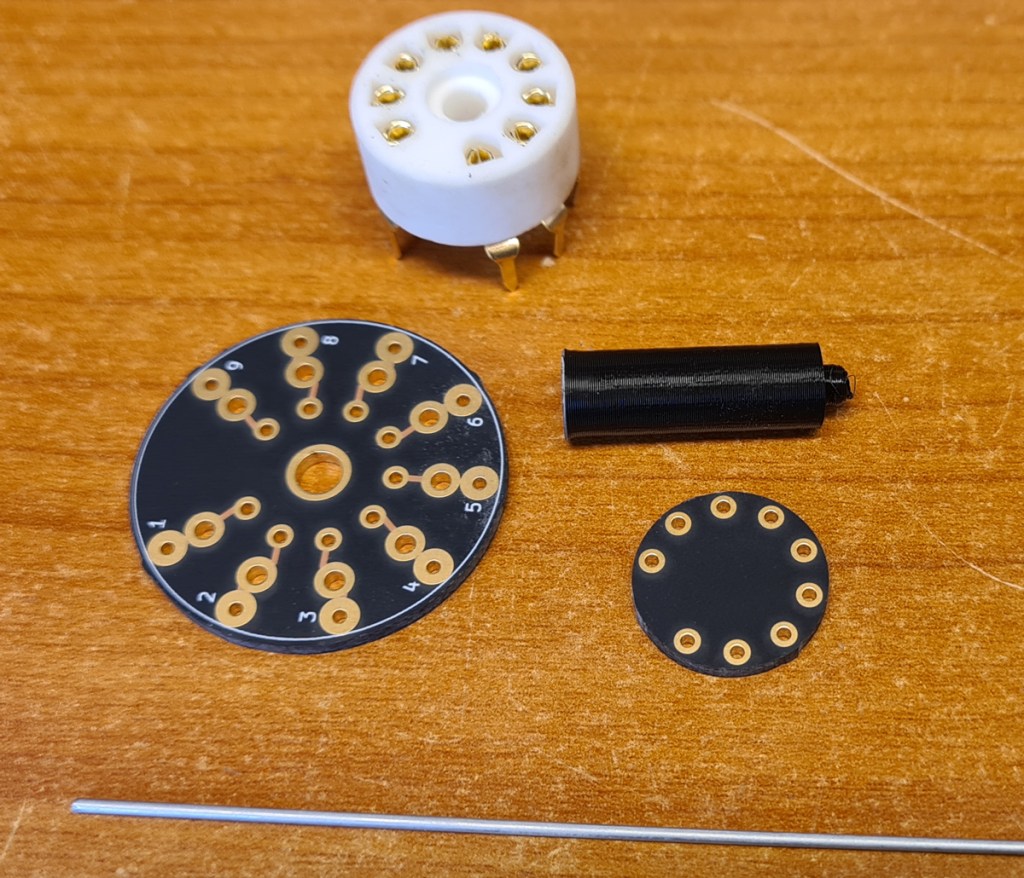
Instead of spending a lot of money on old test sockets, I decided to make my own noval test sockets, and I might as well share design docs and description with you. The solution is based on two small PCBs, to which tube sockets (https://www.ebay.com/itm/191076931572), wire and test rings are soldered. To assemble the two boards at a certain distance, I used some 3D printed plastic parts. PCB design files (Kicad), production files (Gerber) and 3D models (.stl) are shared on Github.

Glue the PCBs and the plastic spacer together as shown. Make sure to align the boards, so that wire may be threaded straight through the holes.
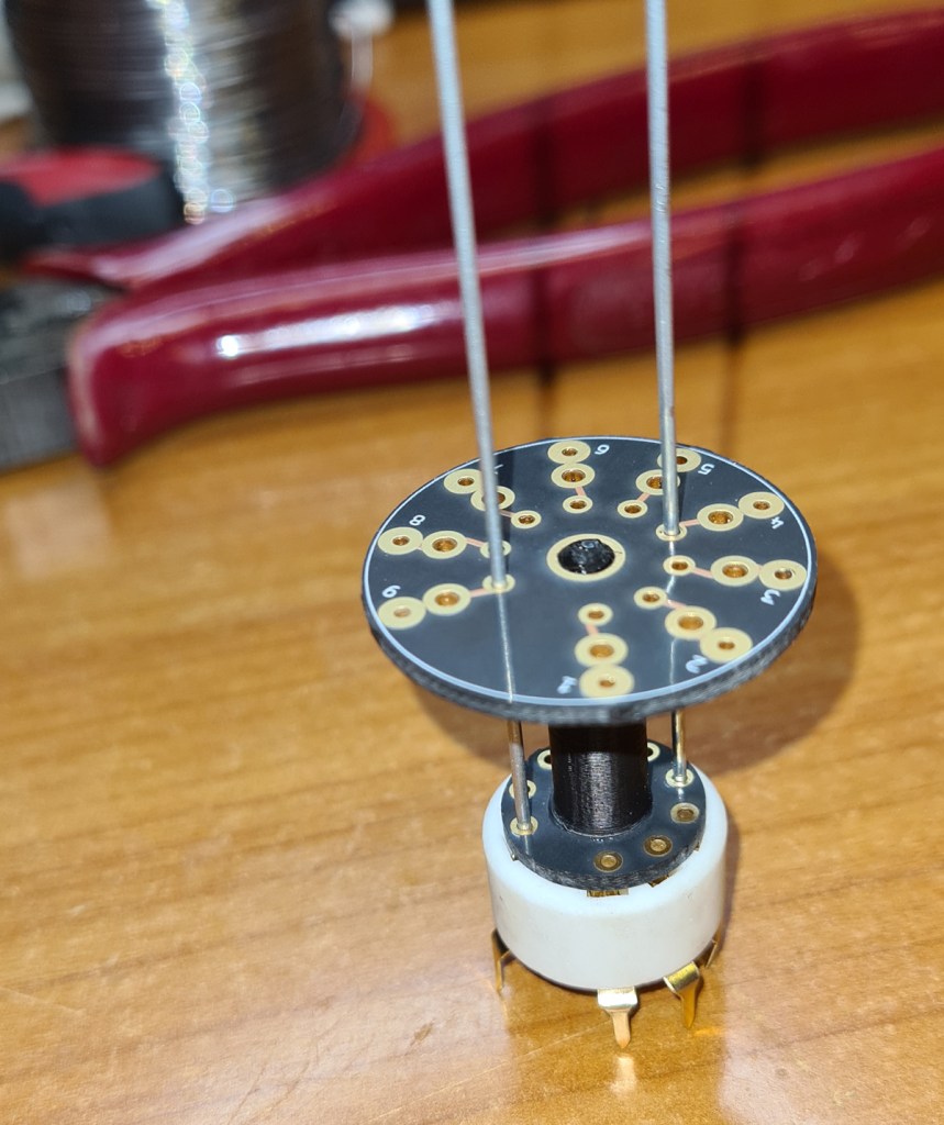
To get the wire lengths right, thread a couple of wires through the top (largest) board board, then through the bottom (smallest) board, and all the way to the bottom of the tube socket, as in the picture.
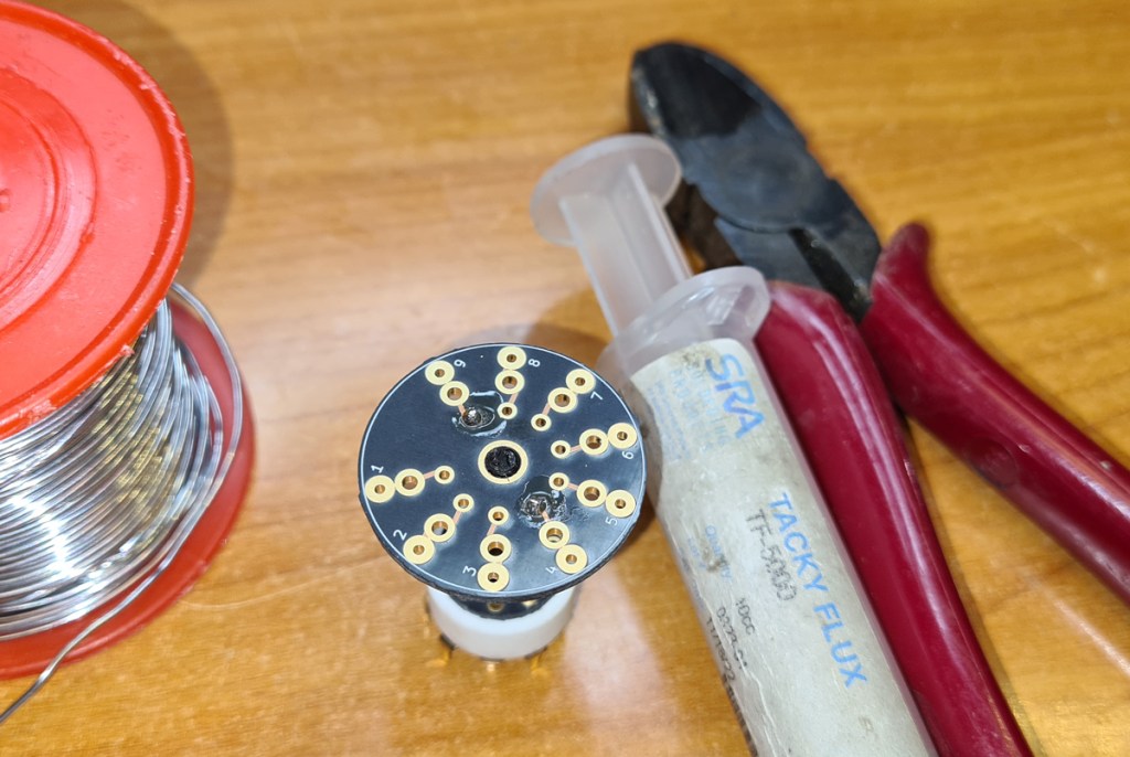
Solder the wires to the top PCB. Some extra flux may be needed, especially if you’re using steel wire. Cut off excess wire right above the top board.

Repeat until all wires are connected, then remove the assembly from the tube socket. Clean off remaining flux with some alcohol.

Flip the assembly around, and solder the wires to the bottom sides of both boards. You may want to shape the wire ends, using a file tool, to make them easy to insert into tube sockets.
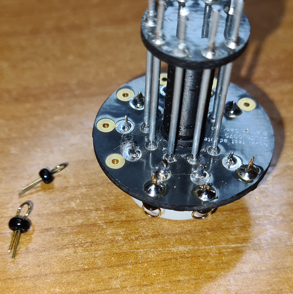
Solder the tube socket to the largest PCB, and then solder test rings (or test pins).

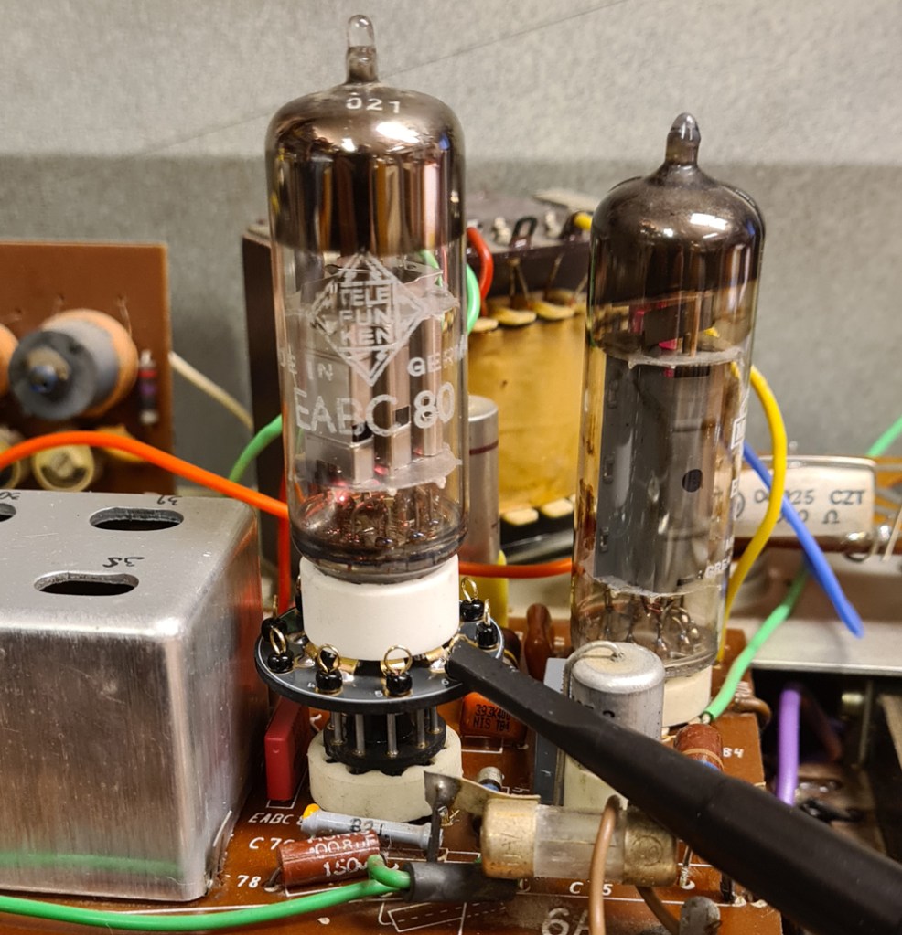
Test socket used when troubleshooting a broadcast receiver, with an oscilloscope probe attached to one of the test rings.
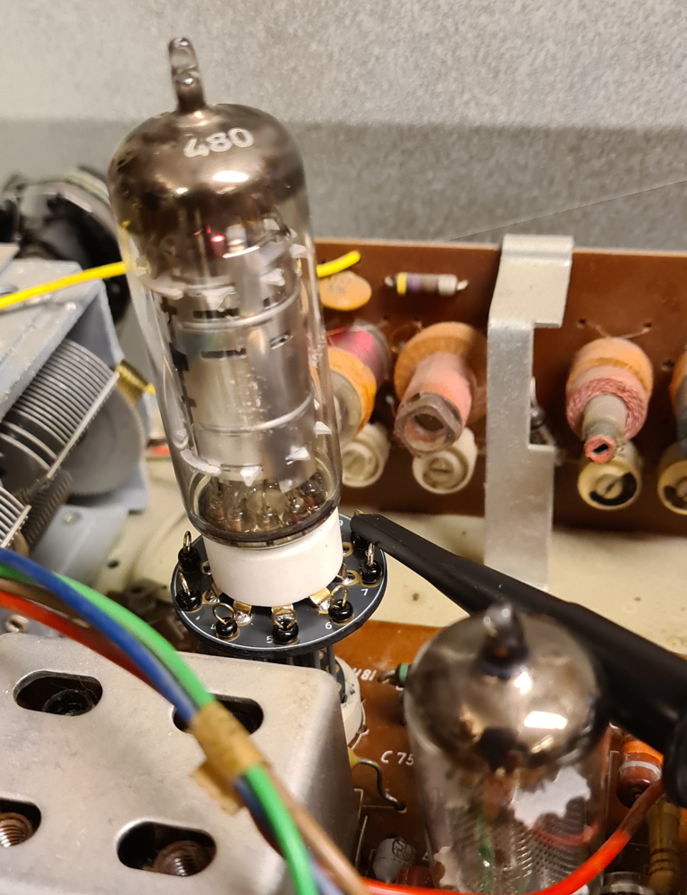
A taller test socket, used to access the pins of a tube which is placed close to a screen box.
Please keep in mind that the inductance and capacitance of the test socket may affect the circuit. This is important when performing tuning/alignment of RF circuits or FM IF (10.7MHz). For high frequencies, a few stray picofarads may shift the tuning frequency noticeably. At audio frequencies or AM IF (typically 455kHz), the influence of the test adapter is smaller.

Leave a comment