
When programming STM32 devices, ST-LINK is my preferred interface for firmware upload and testing.
I started with one of the cheap clones which you get for a few bucks at online marketplaces, and I didn’t like it. These are usually connected to STM32 development board via Dupont wires, which makes it likely that you may occasionally connect it wrong.
In addition, these don’t have a UART interface , so for outputting data to the console/serial monitor with commands like Serial.print(), you may need to connect a separate UART-to-USB-adapter, often called FTDI adapter.
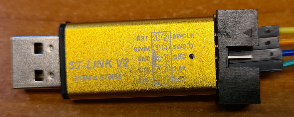
The genuine ST-LINK adapters are probably the best, if you can afford them, but I have to admit I’ve never tried one of those. These is, however a third option, which you may not be aware of:
ST Microelectronics offer a variety of reasonably priced development boards for many of their STM32 microcontrollers, and many of the boards, called Nucleo-xxxx, come with semi-integrated ST-LINK adapters, which may be cut free from the rest of the board, and used separately.

When the ST-LINK is freed from the rest of the board, e.g. using a Dremel with a cutting blade, you’re back to using Dupont wires, unless you make an interface for quick and easy connection to your custom STM32 boards. I designed a simple PCB which connects the pin headers from the ST-LINK board to 8-pin IDC and FFC connectors.
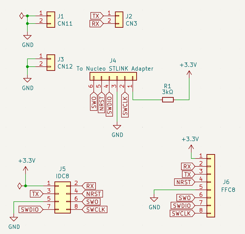
As we can see, the schematic is pretty simple.

On the PCB board, pin sockets are placed so that the pin headers of the ST-LINK fit right into them.
PCB fabrication files (Gerber) and KiCad design files are published to GitHub.
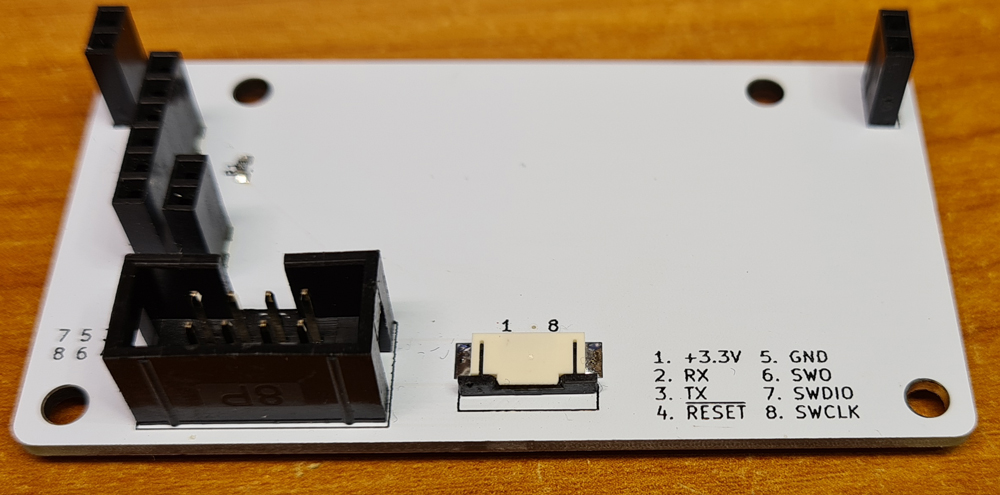
The finished connector board.
The freed ST-LINK adapter needs some modifications:
- Desolder all the pin headers.
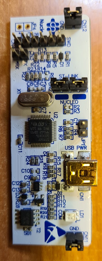
- Solder pin headers CN3, CN4, CN11 and CN12 on the bottom side of the board. Now it shall look something like this:
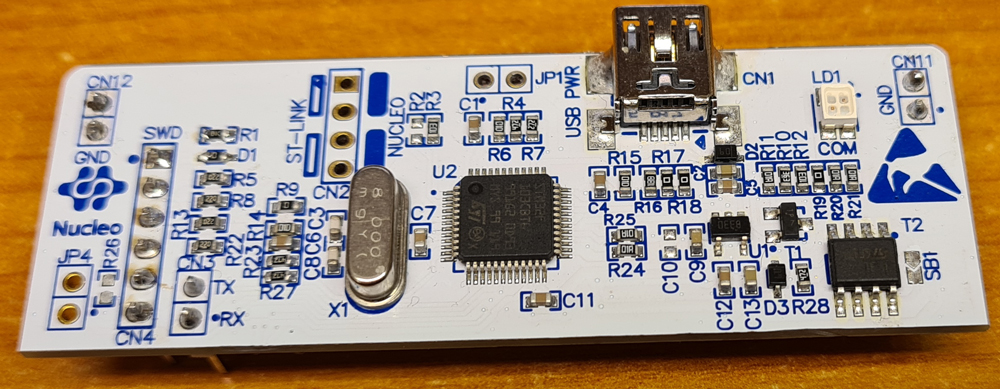
I do also recommend desoldering 0Ω resistors SB12-SB16, to avoid potential shorts on the board edge that you just cut.
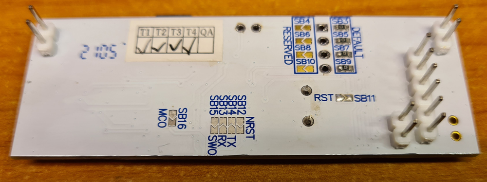
Keep a couple of these resistors for later.
The 3.3V pin of the ST-LINK interface is not for supplying power to your STM32 board, but to measure the voltage of your STM32 supply. A few modifications are necessary to make this work (otherwise the STM32 programmer will complain about the voltage being too low for debugging):
- Desolder D1, and place a 0Ω resistor where D1 used to be.
- Solder a 0Ω resistor on the space for R9.

Plug the ST-LINK into the connector board, and it’s ready for use. For most custom STM32 boards, I use IDC connector, while the FFC connector is added as an option for smaller boards.
Make a 8-pin IDC cable for connecting to custom STM32 boards that implement the same interface. Flat cable from old IDE hard drive cables can be reused for this purpose. Make sure that you don’t mirror the conductors.
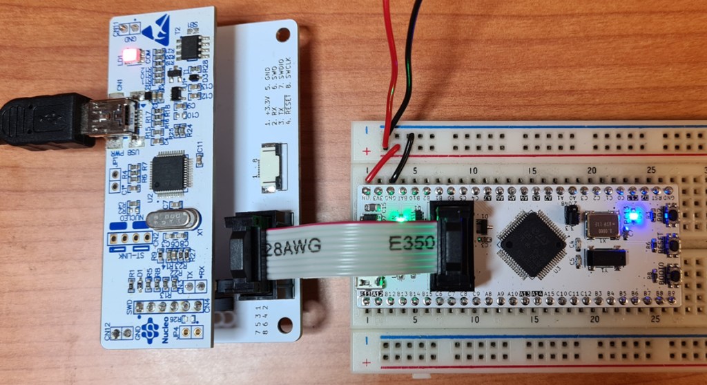
The ST-LINK connected to a WhiteBoard64 development board.

Leave a comment