
One of my planned projects will involve heating elements operating at several hundred degrees celsius, and during development and testing it will need a device that can monitor the temperatures, and disconnect heater power if a firmware- or hardware fault should cause the temperature to exceed, say, 400°C.
One can of course buy such devices, but I thought I’d make one myself, and to make it usable for other purposes, I decided to make it programmable, with the following operating modes:
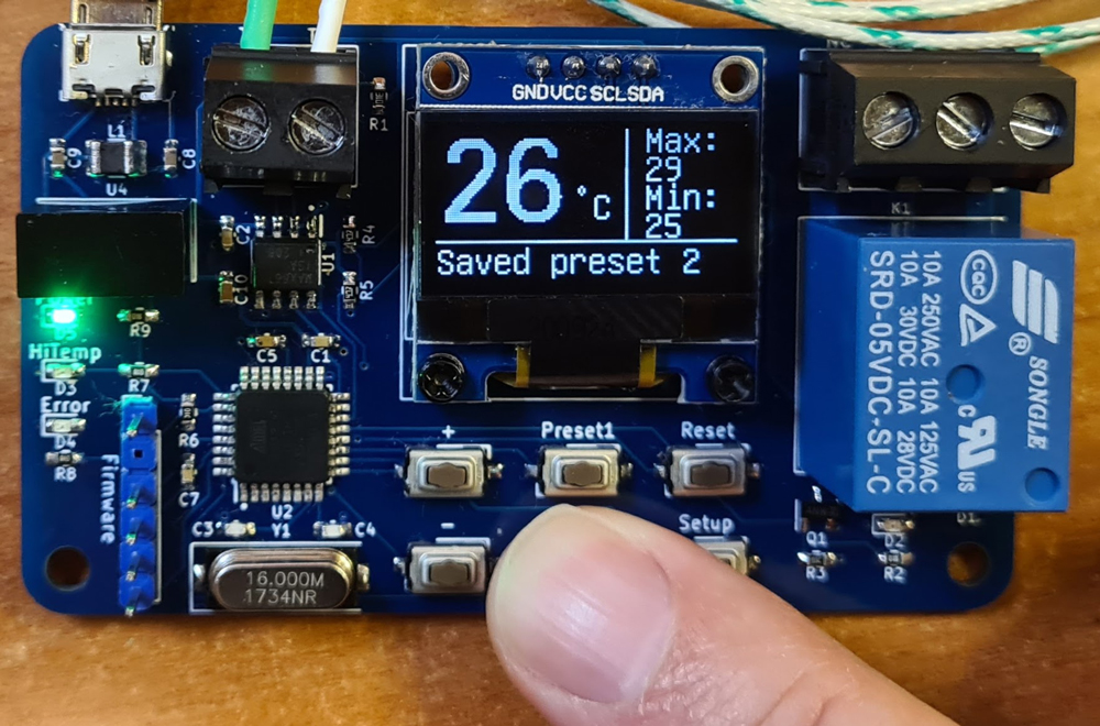
- Thermometer: just presenting the measured temperature on a display, and keeping track of max. and min. recorded temperatures.
- Thermostat: controlling a relay to turn power on or off at a selectable temperature threshold, and with a selectable hysteresis, e.g. turn off a heater when it’s warm enough, or start a fan or other cooling device if it gets too warm.
- Thermofuse: controlling a relay to turn power on or off at a certain temperature, and keeping it in that state until the press of a button.
Thermocouples can be used to sense high temperatures, som of them more than 1000°C, while being reasonably accurate and often reasonably priced.

Thermocouples consist of two conductors of dissimilar types of metal, joined at one end. When heating this junction, electrons break free from their atoms, and are pushed towards the cold junction, causing small thermoelectric voltages along the conductors (the Seebeck effect). These voltages vary with temperature difference between the hot and the cold end, but the ΔV/Δt coefficient is different for different metals/alloys. This makes it possible to measure a small voltage at the cold end, proportional to Δt. If the same metals were used for both conductors, the two voltages would cancel out each other, and the meter would show 0.
The K-type thermocouple, which I will use for this project, is made of chromel and alumel, and delivers approximately 41 μV/°C. Such small voltages need to be amplified before being processed by an A/D converter. Precision OP AMPs can be used, but there are also IC’s specially made for amplifying and digitizing thermocouple sensor voltages. I went with the MAX6675, which has a 12-bit DAC, SPI interface, and a built-in cold junction compensation. The IC allows temperature measurements up to 1024°C, but for now, I’ll be using a reasonably priced K-type thermocouple which “only” ranges up to 600°C.

With the hot junction exposed like this, the sensor reacts rapidly to temperature changes, but it’s less rugged than enclosed sensors, and the bare metal ends are not electrically isolated from the object of which the temperature will be measured. To address the latter issue, I’m adding galvanic isolation in the thermostat’s power supply.

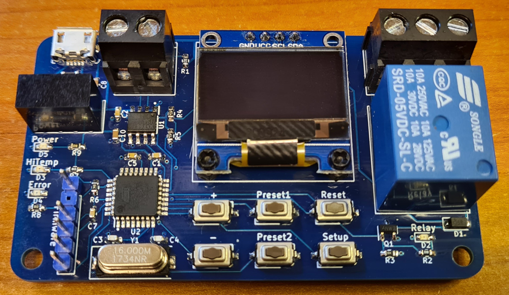
The circuit is pretty simple: A USB micro connector is used for 5V power input, allowing an old cell phone charger to be used as supply. Galvanic isolation is achieved by a B0505S isolated DC converter. The microcontroller is a trusty old ATMEGA328P-AU, which retrieves data from the MAX6675 thermocouple sensor IC via SPI, and which controls a 0.96″ OLED display through I2C. The MCU controls a relay and some status LEDs, and there are push buttons for adjusting threshold temperature, navigating the Setup page, saving and retrieving presets (stored in EEPROM), plus a Reset button. A pin header allows firmware to be uploaded via UART, using a so called FTDI adapter (readily available from marketplaces like eBay).
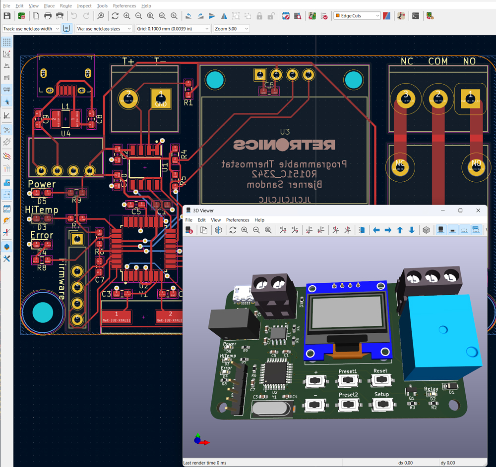
PCB manufacturing files (Gerber) and KiCad design files are shared on Github.
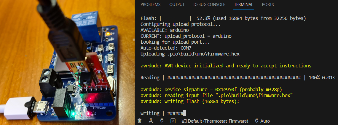
Before soldering the ATMEGA microcontroller, you must burn bootloader.
The firmware is written in PlatformIO on VSCode, a better code environment than Arduino IDE, but still using the Arduino framework. If you haven’t tried PlatformIO yet, this is a good time to check it out. There are lots “Getting started with PlatformIO” tutorials on YouTube.
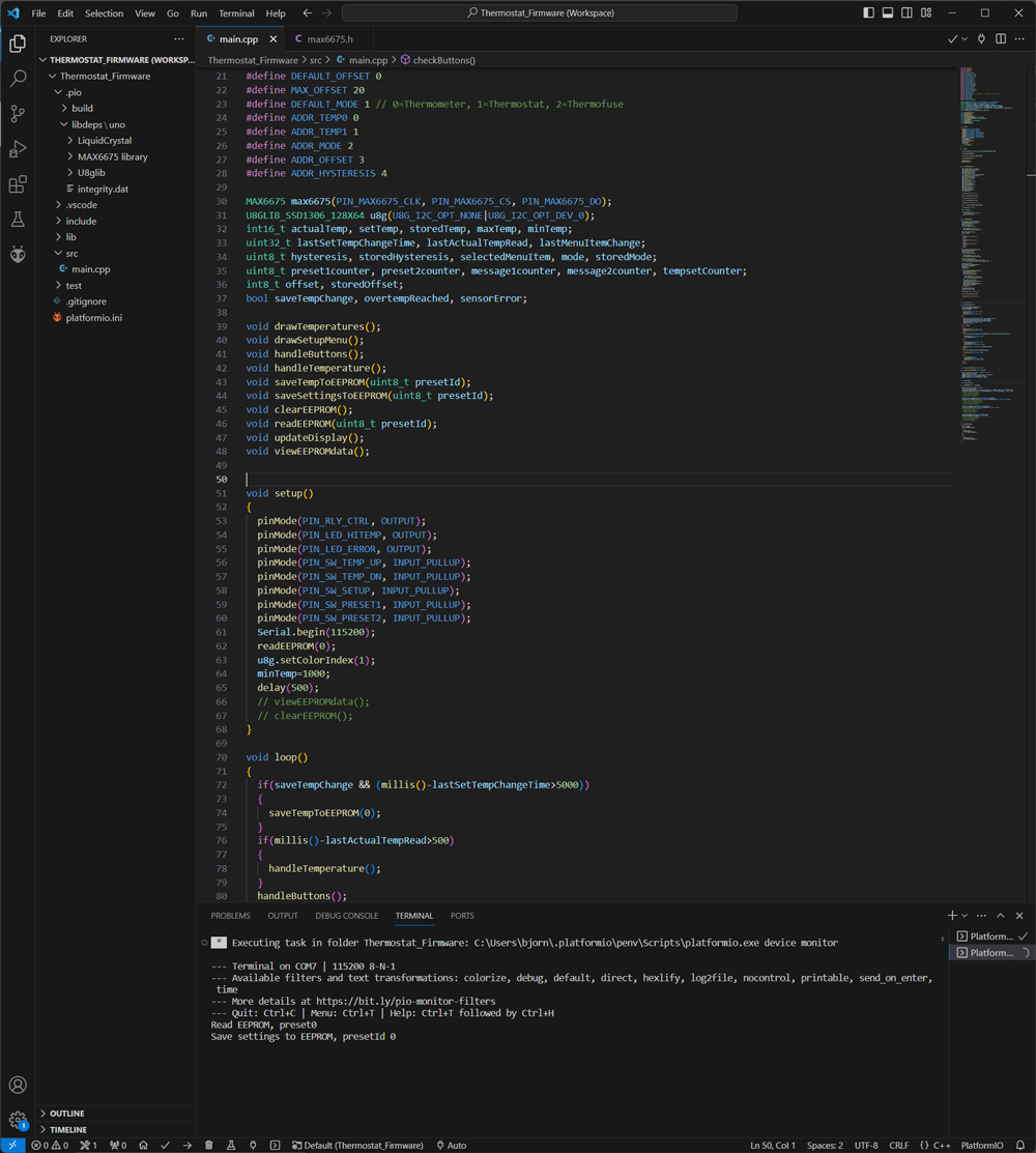
Code is shared on Github.

Press Setup to navigate through the settings and +/- to change selected property.

In Thermometer mode, the relay is always off.
In Thermofuse mode the relay is on as long as actual temperature is below selected threshold. When threshold is reached, the relay turns off and HiTemp LED turns on, and these states are kept until Reset button is pressed.
The Offset setting is used for calibration.
Settings are automatically stored to EEPROM, and retrieved next time you power on the device. In addition, two sets of settings can be stored and retrieved, using the Preset buttons.

Leave a comment