
Sølvsuper 3 was manufactured in Oslo in the WW2 years 1941-1945. In that period, Norway was occupied by Germans. Radio receivers were a means of receiving information from Great Britain and other allied countries, and were prohibited by the occupant forces. Still, Tandberg were allowed to build broadcast receivers in those years, for shipping out to the customers after the war had ended.
Sometimes, I’m less fortunate with the restauration objects i receive. This one came with a broken dial glass, deformed bakelite frames and a cabinet with lots of scratches. Still, could be worse…

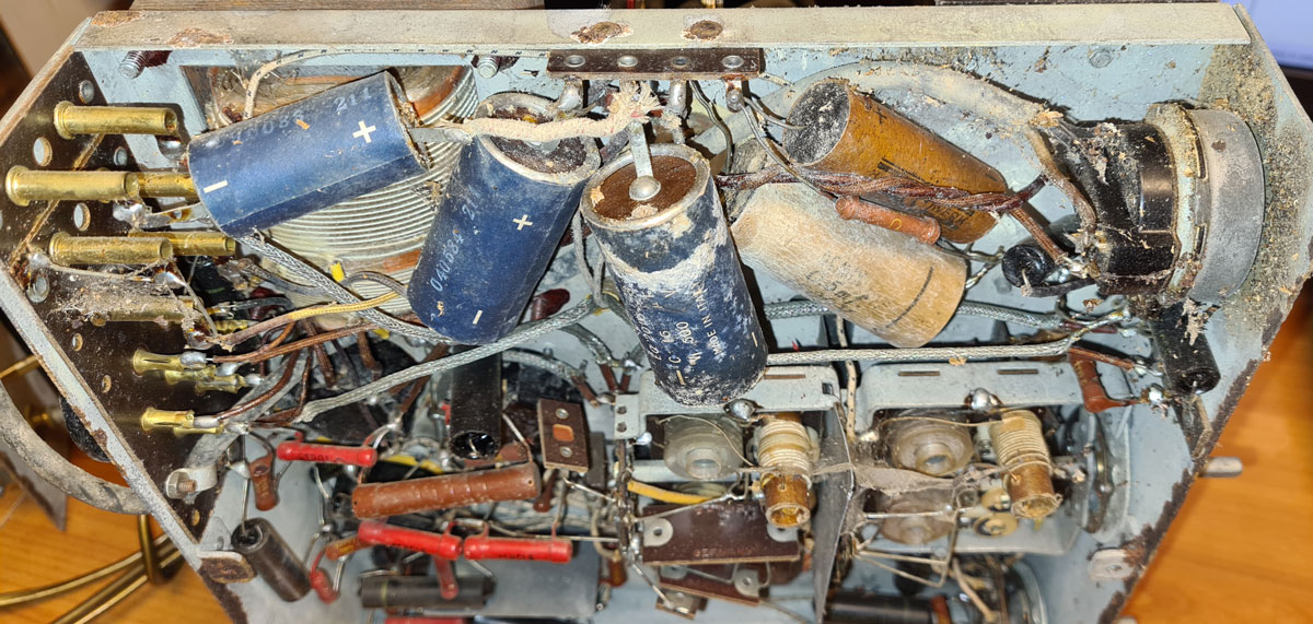
…and on the inside, it was worse. Decades of storage in humid environments had left the radio rusty, rotten and moldy. There were also evidence of half-hearted repair attempts. From the look of the blue electrolytic caps, I believe this must have been in the 60s. The repairman had actually used the shields of internal coaxial cables as ground connections for the PSU smoothing caps. If that didn’t cause lots of hum due to ground loops, it must have been pure luck.
The speaker both looked and sounded horrible, and its veneer mounting plate had disintegrated.

I that condition, the best I could do was put it aside and use it as parts for restoring a better object.
Later, I came across an other SS3, which didn’t look so bad on the outside. On the inside, however, it was just as bad, or maybe even worse than the first object.


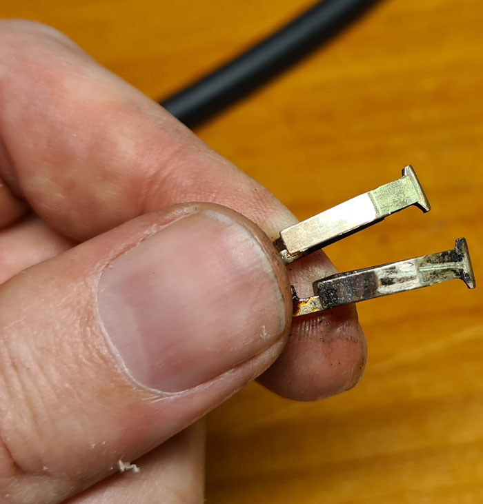
Earlier, unqualified repair attempts had left soldering joints like this. Also the audio in- and output terminals of the volume potentiometer had been mixed up, so the volume adjustment must have been suboptimal, if the radio even worked at all after that repair attempt.
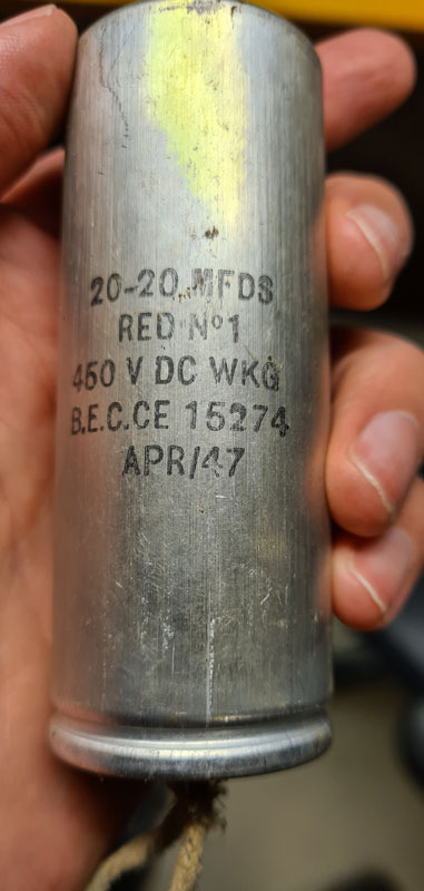
Over the years, the radio has most likely been through several stages of hum. The dual smoothing cap is labeled APR/47, so I’m guessing that the original cap had been replaced relatively early in the radio’s lifetime. It’s mounting bracket didn’t fit the chassis holes, so it wasn’t mounted properly.
Later, an other electrolytic cap had been placed in parallell with the aforementioned, most likely in the 60s or 70s. Notice the solder joints 🙂

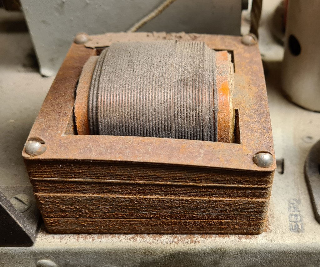
The output transformer was actually so rusty that it had lost it’s original shape. This made me decide to change the roles of the two objects; the previously acquired radio was promoted from parts donor to repair object, and the more recently acquired one would be sacrificed for parts.

Apart from these horrible connections, the second radio’s loudspeaker was in reasonably good shape. The parts donor also had an intact dial glass.
From the two objects, I could then gather almost all necessary parts, except volume potentiometer with built-in power switch (the switch was broken on both), EFM1 magic eye/pentode (both were dim), plus standard components as capacitors and resistors.
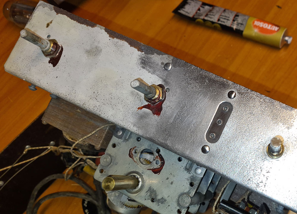
Cleaning, rust removal and polishing.

There was no hope of reforming the old electrolytic caps, so I re-stuffed the capacitor can from 1947 with new 22 and 47µF electrolytics. These are higher values than original 16 and 24µF, but still within what the rectifier can handle (AZ1 is rated for max 60µF on first smoothing cap, and now the first smoothing cap is 22µF).
I modeled and 3D printed a threaded mounting bracket and nut, to make it fit the mounting hole in the chassis.

I haven’t seen the original dual cap and its mounting bracket, but by looking at other radios from the same era, I’ve got reason to believe that the new bracket closely resembles the original, except it’s made of ABS plastic instead of bakelite.
This time the smoothing caps’ minus poles have got a solid chassis connection, in contrast to the aforementioned caps which someone had installed with internal coax cables’ shields as ground connections.
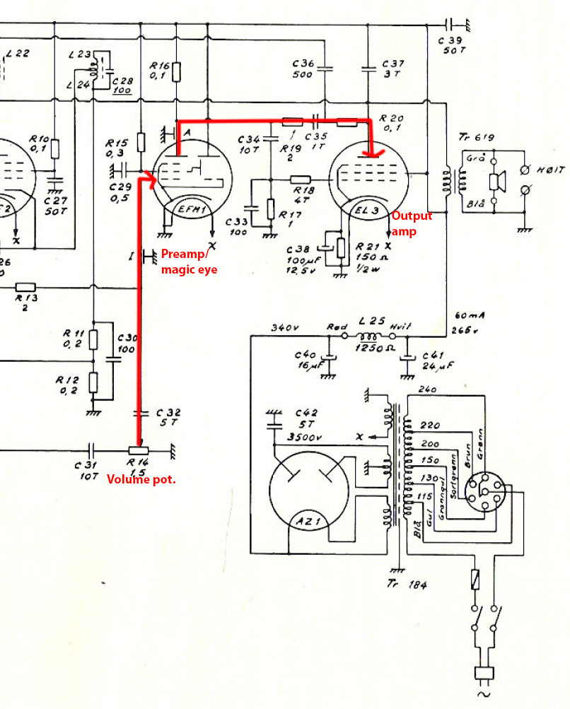
On Sølvsuper 3, the “premp” pentode and magic eye are contained in the same glass tube. This means that the audio path goes from underneath the chassis, up to the magic eye close to the top of the radio, and then back under the chassis.
Both original EFM1s were dim, but I got a NOS replacement from eBay.
As usual with radios from this era, all paper/wax had become leaky, and I replaced them with new polyester caps.
The tube sockets’ brass pins were covered in thick layers of corrosion and dirt, more than Q-tips and alcohol could handle, so I had to extract all pins, clean and polish them with Dremel and a brass brush, and re-insert them to the bakelite sockets, to achieve proper connections to the tubes.

At first the radio’s sound was affected by hum and other noise, which I struggled to find the cause of. I noticed, however, that on all coaxial wires, the shield had been unraveled a couple of cm on each end, adding up to quite a long distance of unshielded signal cable. In high impedance circuits like this, the unshielded parts of the signal paths are likely to pick up a lot of noise.
I replaced all internal coax’es with new, and let more of the shielding be intact. This significantly improved signal/noise ratio.
An other phenomena I noticed, is that when the radio was tuned to a station which broadcasted music, the bass was audible even when the volume was turned all the way down. If I adjusted the volume just a tiny bit over 0, I could hear treble and midrange, while the bass vanished. Not a big deal, but out if curiosity, I decided to locate the cause and (if possible) do something with it.
The reason for this issue could be traced back to how the AGC (automatic gain control) was designed. In SS3, AGC works backwards to mixer and IF amplifier, but also forwards to the pentode part of EFM1 (the audio preamp).

The AGC control voltage comes from a detector diode in EBF2 and is low-pass filtered by R8 (1MΩ) and C24 (50nF). With these values, the filter has a cut-off frequency of about 3Hz, which may seem low enough to prevent low frequency audio from affecting AGC, but the RC filter doesn’t have a very sharp cut-off, so a small but noticeable amount of bass is passed through. The audio signal and the AGC DC voltage follows the same wire to the control grid of EFM1, where the AC is amplified and the DC is used for both gain control and visual presentation (magic eye). With a little bit of bass being passed though the AGC RC filter, this becomes audible when the volume pot is turned to 0.
I increased the value of C24 to 180nF to move the AGC cut-off frequency down towards DC, and the unwanted bass was as good as eliminated. A side effect of this is that the AGC and the magic eye reacts a little bit slower, but I found this solution to be a good compromise.

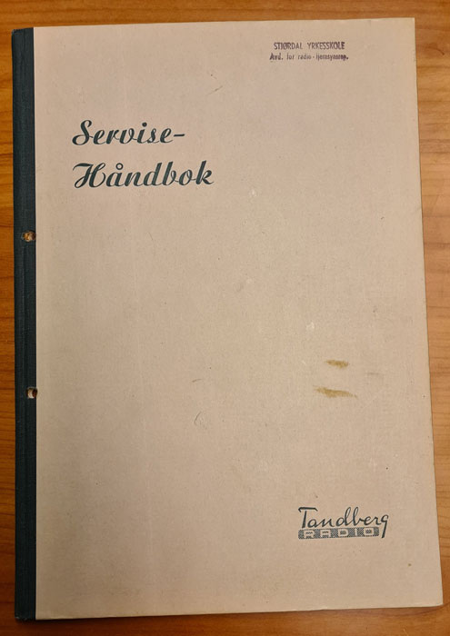
Trimming the IF filters, by following the guidelines in the Tandberg Service Handbook, which covers broadcast receivers from 1933 to 1948. I was lucky enough to get an original hard copy, but the book is also available online, as pdf.

When trimming the RF filters, I used a homemade step attenuator between the function generator and the radio’s antenna input, since my generator only goes down to 1mV.
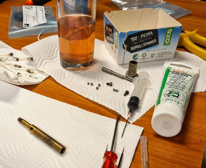
The tuning shaft, with internal 5:1 reduction gear, was stuck in hardened grease, so I had to disassemble it, and let the parts soak in alcohol for a few hours, before cleaning, lubrication and re-assembly. With quality ball bearing grease, this should run smoothly for decades.

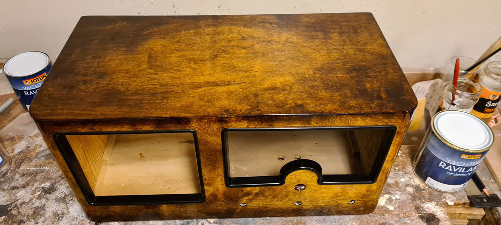
On the cabinet, old crackled varnish was stripped off, first chemically using Liberon stripper, and then with sanding paper.
The shaded areas were re-created with Herdins Lakkbeis (stain) in color Dark Oak, mixed 50:50 with alcohol, before applying a total of 8 coats of Jotun Ravilakk (amber varnish), to create a golden appearance, and then polished to high gloss.

The original rear covers were ruined on both radios, one by rot and one by some vandal who had made a cut for connecting an external loudspeaker. I made a new plate of plywood, and with Herdins Lakkbeis Dark Oak, it looks pretty much like the original.

The bakelite buttons got their white markings back, by applying Bengalack with a tooth pick.
Buttons and frames were polished with bees wax.

One one radio, the speaker grille fabric was rotten. On the other the fabric was reasonably intact, but inseparable from a rotten piece of plywood. Therefore, I had to buy new fabric, which doesn’t look like any of the old ones, but at least it looks nice 🙂


Leave a comment