
When aligning vintage radio receivers, I’m using a Siglent SDG2122X as signal source. It can deliver signals up to 120MHz, with several modulation types (AM, FM and others). This is a great function generator for this use, with one minor drawback: the lowest output amplitude is 1mVPP. For RF alignment, this is way too much. Therefore, external attenuation is necessary.

One could of course use fixed BNC attenuators, but these can be rather pricey, and you’d have to plug and unplug several of these to achieve the desired attenuation. A variable attenuator with several steps would be helpful for RF alignment, and I don’t need a high precision or high power device for this, so I thought I might make one myself.
Cascaded resistor networks, which segments that can be bypassed by switches, can be used to form a step attenuator.
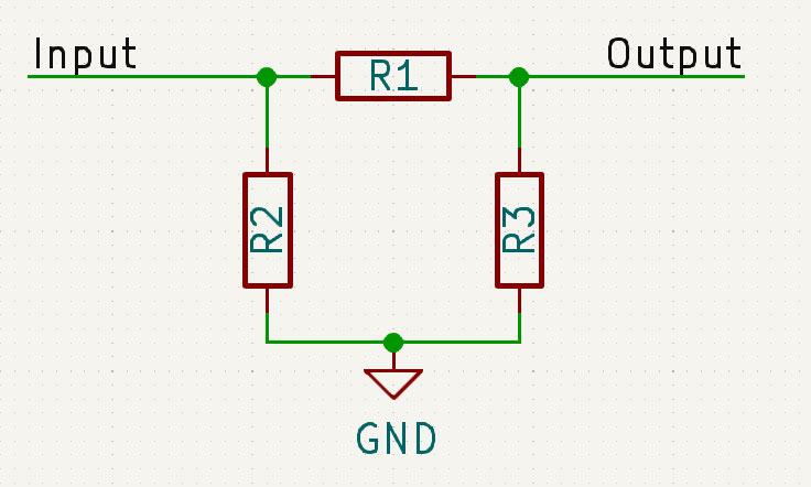
To maintain desired input- and output impedance, each segment is built as a symmetrical pi network. When input- and output impedance shall be the same, R2 and R3 are equal.

You may calculate resistor values manually, but for simplicity, there are lots of online calculators you can use, e.g. this: https://leleivre.com/rf_pipad.html
I selected 50Ω impedance and 10dB attenuation, and the calculator proposed resistors values of 71.151Ω and 96.240Ω.
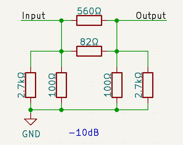
Instead of buying resistors with unusual values, I used standard values in parallel, to achieve something reasonably close:
560Ω || 82Ω = 71.53Ω
2.7kΩ || 100 Ω = 96.43Ω
With a cascade of three such stages, resistor values calculated for -10, -10 and -20dB, and each stage possible to bypass with toggle switches, a total attenuation of 0, -10, -20, -30 and -40dB is selectable.


For RF alignment and sensitivity measurements of AM broadcast receivers, it’s recommended to use a standard dummy antenna between generator and antenna input terminal. This picture is taken from a Tandberg service handbook (in Norwegian), but you’re likely to find something similar in other textbooks.
Since I was making a step attenuator specially for the purpose of testing and calibrating old broadcast receivers, I decided to include the dummy antenna on the same circuit board. Closest standard component values are used.


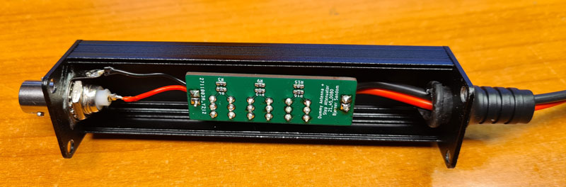
PCB design in KiCad. Design files and Gerbers are published to Github: https://github.com/donpivo/StepAttenuator_DummyAntenna
The finished board, mounted in an aluminium project box, with 50Ω BNC input connector. I can’t find the exact same box on eBay now, but this seems to be a good alternative: https://www.ebay.com/itm/193727391474
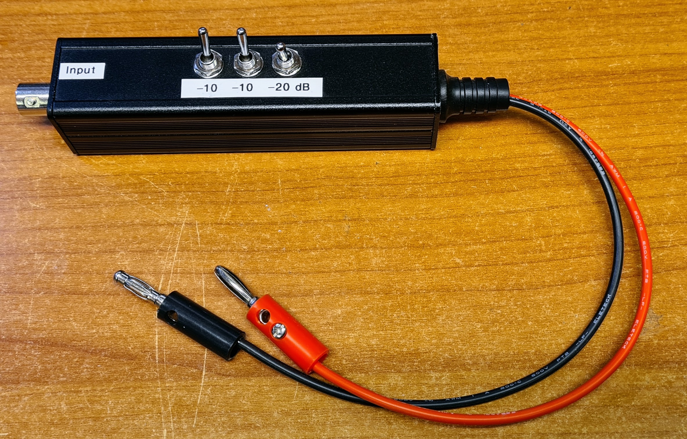
The finished step attenuator with integrated dummy antenna.
Since most of my old AM radios have 4mm jacks for antenna inputs, I used banana plugs.
This is not a high precision device, but for RF alignment of AM broadcast receivers, this works perfectly for me. If the alignment initially is way off, I may start with zero attenuation, and as the alignment gets closer and the radio’s sensitivity enhances, I reduce the signal in steps of 10dB.

Leave a comment