
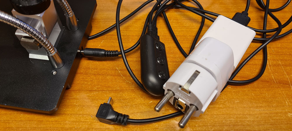
Time to get rid of the separate power button, dimmer, mains adapter and cable mess…
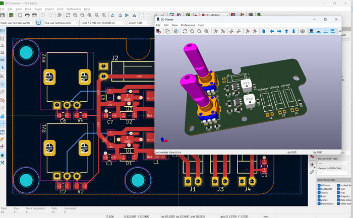
The introduction of a LED ring (in previous post), in addition to the LED spotlights, entailed the need for a dual LED dimmer, so I just made one, based on switched LED driver IC AL8861Y-13 from Diodes Inc. The circuit design is pretty simple: just follow directions in the datasheet.

The two dimmer circuits are equal, except for the values of current sense resistors R1 and R3. These define max output currents, which will be applied when potentiometers are rotated max clockwise, and which will drive the two paralleled LED spots and the LED ring respectively. Resistors values are calculated from a simple equation: 0.1V / Imax. With the original dimmer connected, the LED spots drew approx. 500mA at max brightness. The same current is target max output for the new dimmer, hence R1 is calculated as 0.1V/500mA = 200mΩ. On the LED ring, there are 9 LEDs, which each have a max current rating of 120mA, causing a max total of about 1A. There is no need to drive the LEDs at max power, so I set the value of R3 = 120mA, limiting the current to 0.1V / 120mΩ = 833mA.
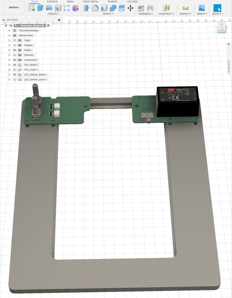
I made a simple PSU with same PCB form factor as the dimmer:
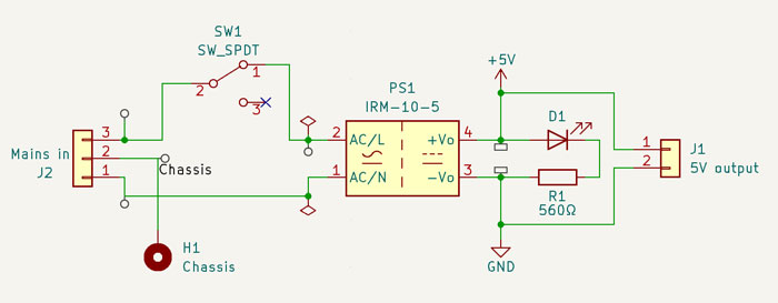
An IRM-10-5 switched PSU from Mean Well does the job. It takes anywhere from 85 to 264 VAC in, and delivers 5 VDC and up to 2 A out. I measured the current draw of the microscope (camera and screen) to be 500mA. With max. LED currents of 500mA and 833mA, the total max. current draw adds up to 1833mA.

The finished PSU board, with power switch and status LED (a side-view LED, pointing towards the user). For security reasons, mains earth is to be connected to the Andonstar steel base, via the mounting hole on the left side of the PCB, through an M4 brass spacer to existing mounting hole in the steel base. Be careful not to touch the board when mains power is connected.
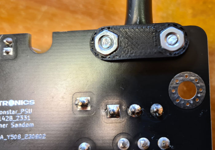
Picture of PCB bottom side. A strain relief must be used, to securely fasten the mains cable to the PCB. .stl files for the strain relief upper- and lower parts can be found along with other models on Github. I printed them using ASA filament for strength.
M3 screws and nuts hold the pieces together.
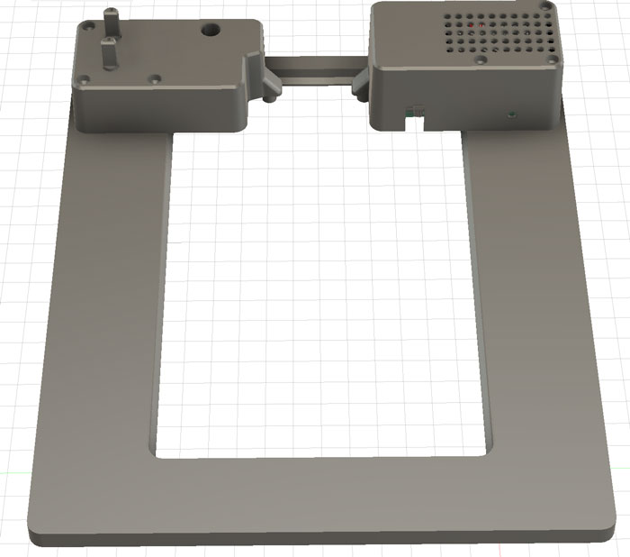
The original Andonstar base platform is too small to give proper support when inspecting larger PCBs. Therefore, I modeled a base extension which will surround the steel base. This extension also has mounting holes for PSU and dimmer PCBs and covers, and a concealed tube for wiring between the two boards.
With a size of 200x240mm, the extension just fits into the plate of my Prusa MK3S+. You may have to check the size capabilities of your printer before starting.
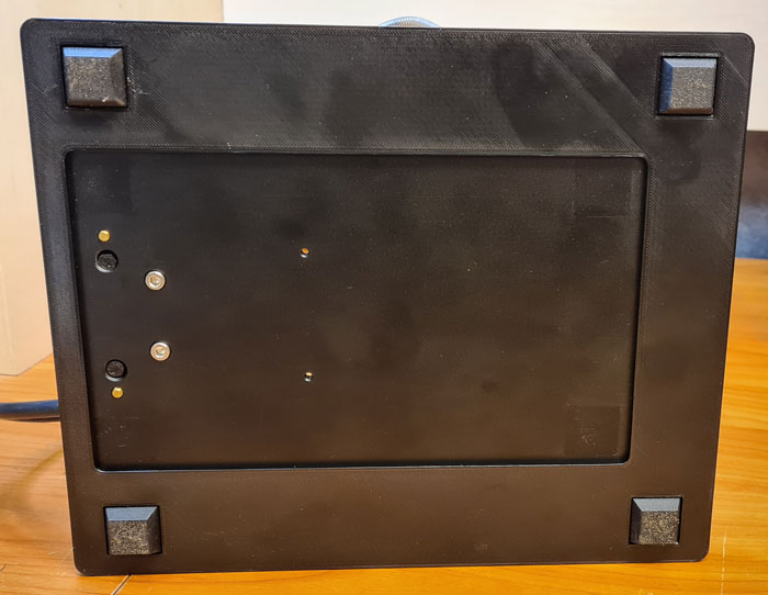
Bottom side of the base. The steel base fits tightly into the extender, hence to fasteners are necessary. Original rubber feet are moved to the plastic extender.
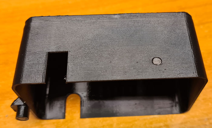
The PSU cover has a small hole in front, through which the power LED can be seen when the unit is on. For enhanced visibility, I glued a small piece of acrylic rod inside this hole.
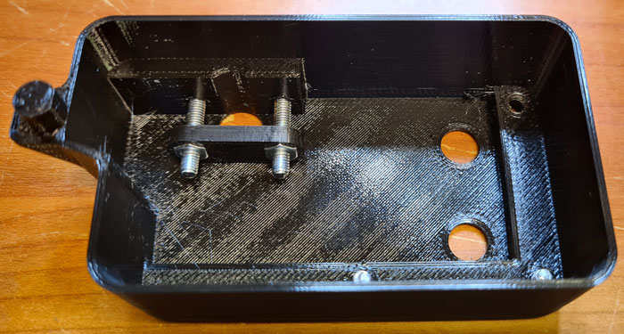
Inside the dimmer cover, add a strain relief (StrainRelief_Bottom.stl) with M3 screws and nuts, as shown in the picture.
Continue to Part 3 for assembling the pieces together.

Leave a comment