
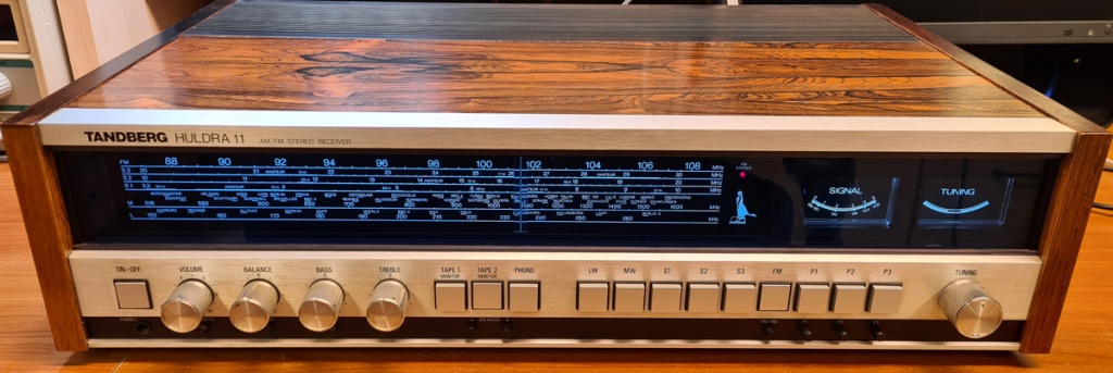
One of the younger radio receivers in my collection is Huldra 11, which was manufactured between 1976 and 1978, and I use one of these on daily basis in my workshop, accompanied by a couple of Tandberg TL2520 loudspeakers. This receiver model generally has few problems, and the capacitors and most other components usually are in good condition, even after almost five decades. There are, however, a few issues that you may have to address, to make the receiver work flawlessly for decades to come:
1. Replacing transient suppression capacitor on mains input
On the primary side of the mains transformer, there is a Rifa 10nF capacitor for noise/transient suppression. These caps have a tendency to get leaky, overheat and go up in smoke. Therefore, I recommend always replacing the Rifa with a new X2 classified capacitor before connecting the radio to mains.

2. Rewiring the mains transformer for 240V (in countries with 230V nominal mains voltage)
Most Hulda 11’s are originally wired for 220V operation, while mains voltage in most of Europe typically is around 230V nowadays. This causes slightly elevated voltages on the transformer’s secondary windings; not enough to harm the electronics, but it may reduce the lifetime of incandescent lamps. Rewiring the mains transformer for 240V input may be a good idea. On the picture above, the transformer is shown with 220V wiring (left) and with 240V wiring (right). Please note that Huldra 11 were manufactured with two different transformers, which are wired differently. Correct wiring is shown in the service manual.
3. Cleaning the speaker protection relay
Some owners of Huldra 11 may experience that the sound from one (or both) speaker outputs fall out occasionally. This may be due to dirt or corrosion in switches or potentiometers, which is a common failure mode on most old electronics, but it may also be caused by corroded contacts on the speaker protection relay. On the Huldra 11 that I’m using daily, this was a problem cause, and I tried opening the relay and cleaning the contacts manually with different cleaning agents, but the problem soon reappeared. A method that did work, however, was to apply a cleaning & lubricating spray to the contacts, and feed the relay coil with square pulses, making it switch off and on rapidly, while the contacts are rubbing against each other.
The spray I used is EML Electrolube, and the process took a couple of minutes. It’s been 18 months since this cleaning was performed, and the relay has been working flawlessly since then.
4. Preventing pops or bangs on speaker outputs at startup
When the receiver is turned on, the output amplifier stages will have large voltage swings (all the way from positive to negative supply rail) for the first couple of seconds, before stabilizing at 0 VDC. During this time, the output relay is switched off to protect the loudspeakers. A delay circuit turns on this relay after a few seconds, given that little or no DC is detected on the amplifier outputs. On some receivers the relay can turn on too rapidly, causing a voltage transient on the speaker outputs, which can be highly audible.
I made a single capture on the oscilloscope to show what’s happening during startup:

Yellow trace (10V/div) shows the voltage that comes from one output amplifier stage and into the relay. As we can see, there are major voltage swings. After about 3 seconds, the amplifier has stabilized at 0VDC.
Pink trace (1V/div) shows the output from the relay, which is connected to the speaker terminals. The vertical dashed lines mark the times when the amplifier is turned on (left) and when the relay switches on (right), and the time interval between these is 2.5 seconds. As we can see, the relay turns on before the amp has stabilized at 0VDC, and this causes a transient of about 300mV on the speaker output, which is audible and therefore annoying.
The solution is to increase the delay time of the speaker protection circuit by changing the value of C773 from 22µF to e.g. 47µF.

5. Replace and protect ceramic filters to improve FM reception
In the FM receiver of Hulda 11, three ceramic bandpass filters are used in the IF section. These have a tendency to deteriorate over time and cause poor FM reception. By just replacing the filters with new Murata ceramic filters with 10.7MHz center frequency and 230kHz bandwidth, one will instantly improve reception, but the problem is likely to reappear after some years.

The cause of the deterioration is that these filters are not designed for handling DC, but in Huldra 11 (and lots of other radios), they are exposed to several volts DC. To make the filters last longer one can block out the DC by adding coupling capacitors on the input- and output terminals. To make this modification tidy, i made small PCBs, on which two 10nF capacitors (0805 package), the ceramic filter, and some pin headers are soldered:

These boards fit nicely into the FM tuner board:

To visualize how much FM reception improved with new filters, I tuned to a certain radio station, and took pictures of the signal meter before and after filter replacement:

Before the modification, only one radio station was received in stereo, but now I’m getting stereo reception on several channels, despite using just a cheap wire dipole, placed in my workshop in the basement (i.e. surrounded by armored concrete).

Leave a comment