

Replacing lightbulbs is not the most exciting thing to do with a radio receiver, and incandescent lamps are getting less available and more expensive. For radios which are in daily use, and which doesn’t necessarily have to be 100% original, using LED illumination may be a good solution. The simplest solution may be to buy LEDs with traditional lamp sockets and internal drop resistors. I don’t like that, because when feeding these with 50Hz AC voltage, the flickering is noticeable. In half of each AC cycle, the LEDs are reverse biased with voltages reaching reverse breakdown voltage. Getting the right brightness and color temperature may also be a challenge.
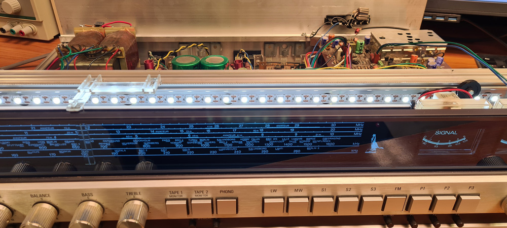
On Huldra 11, where the dial glass is blue tinted, LED color temperature is not an issue, and cold white LEDs may be used as well as warm white. To create an even background lighting all across the tuning dial, I chose LED strips with 60 LEDs per meter and 5V nominal voltage.

I cut off a strip with a total of 27 LEDs to cover the whole width of the dial.
As on many other receivers, the dial lamps are supplied with around 6 VAC from the mains transformer. This needs to be rectified and filtered. I also wanted to be able to adjust the light intensity, so I made a little circuit for this purpose:

The circuit should be pretty much self-explanatory. The voltage regulator is an NCP1117 in adjustable version, which can deliver up to 1A. Resistors R1, R2 and potentiometer RV1 is calculated for a variable output of about 2 to 4.4 volts, which is adequate for adjusting the LED strips to suitable brightness. 5V would be too bright and consume too much current.
With a strip of 27 LEDs, and output voltage set to 4.4V, the measured current draw was 550mA. With this load, the output of the rectifier was 5.8V. From these values, we can calculate that the NCP1117 will have to dissipate (5.8V-4.4V)*550mA=770mW as heat. This could have required a heatsink, but I came up with a better idea:
Some PCB manufacturers, like JLCPCB, are capable of making PCBs of aluminium instead of FR4. Aluminium has a high thermal conductance, so boards of this material are good at transporting heat away from components with high power dissipation. Aluminium is also a good electrical conductor, which in this case is unwanted, but a dielectric layer keeps the copper tracks isolated from the aluminum sheet.

I fitted the components on a board of 28x35mm.


This fits into a space in the aluminium chassis on Huldra 11, right beside the board with sockets for the old lightbulbs. Thermal paste between the PCB and the chassis ensures good thermal connection.

LED strip where the old lightbulbs used to be; here driven by around 3V:
To test the thermal behavior of the voltage regulator, I set it for max. output (4.4V), causing a current draw of 550mA, and left it on for a couple of hours. The temperature of the LDO only rose to about 34°C.

For a more comfortable backlight, I reduced the voltage to 3.2V, with a current draw of 200mA.
Design (KiCad) and production files (Gerber) are published on Github: https://github.com/donpivo/Huldra-11/tree/main/Backlight_PSU

Leave a comment