
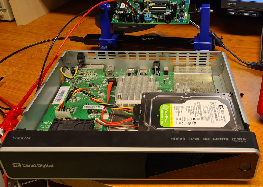
The enclosure of my choice is from a scrapped TV decoder. When possible, I like to incorporate recycled parts in new projects, both of economical and environmental reasons.
During testing and calibration, I noticed that two of the voltage regulators on the µTracer board got uncomfortably hot when using the small heatsinks supplied with the kit. I therefore placed them on a larger, separate heatsink.

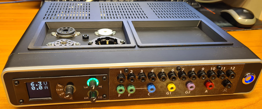
A USB B connector is placed on the rear panel, and connected to the custom USB adapter.
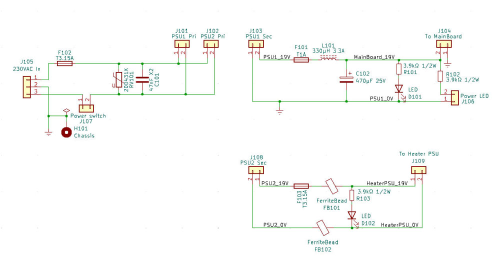
The power supply is based on two 19.5V/3A laptop adapters, which I broke out of their plastic enclosures to save space. These are galvanically isolated on the secondary side; one for the µTracer board, and one for the custom heater supply. The minus pole of the µTracer PSU is connected to chassis ground, while the heater PSU kept floating (hence wrapped in heat shrink, to keep the aluminium shielding separated from the steel chassis).

The mains earth wire is firmly connected to the steel chassis, for security reasons.
A custom PSU PCB provides a rudimentary overvoltage protection on the primary (230VAC) side, and some extra filtering on the power adapters’ secondary sides. The power switch is also connected to this PCB.
The tube sockets were placed on an aluminium board, and this board was fastened to the chassis bottom, using M3 brass standoffs. For now, I used the tube sockets that I had in stock, i.e. octal, loctal, noval and P8A. There is, however, room for adding more sockets later.

Ferrite beads are used on the tube socket interconnect wires, to reduce potential high frequency oscillations.
On the plastic front panel of the enclosure, I made a patch panel for connecting µTracer- and heater PSU outputs to the correct socket pins. I used ordinary 4mm banana jacks, which are not rated for high voltages, but this is not likely to cause any security issues.
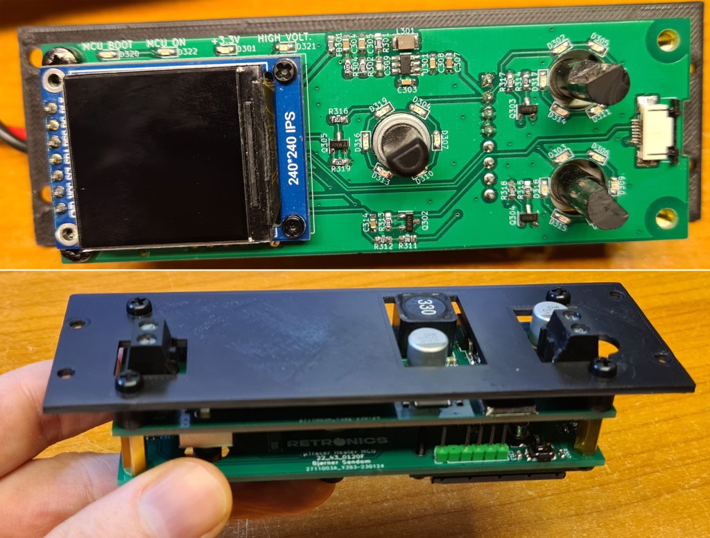
The front cover of the heater supply is also 3D printed, using black ASA with semi-transparent ABS inserts for LED indicators.
The labels are simply printed on thick paper, and covered with adhesive plastic film.
This is just my implementation of the µTracer. On the µTracer website, you will find lots of other ideas and inspiration: https://www.dos4ever.com/uTracer3/uTracer3_pag9.html
The next, and for the time being last post, will show the µTracer in practical use.

Leave a comment