
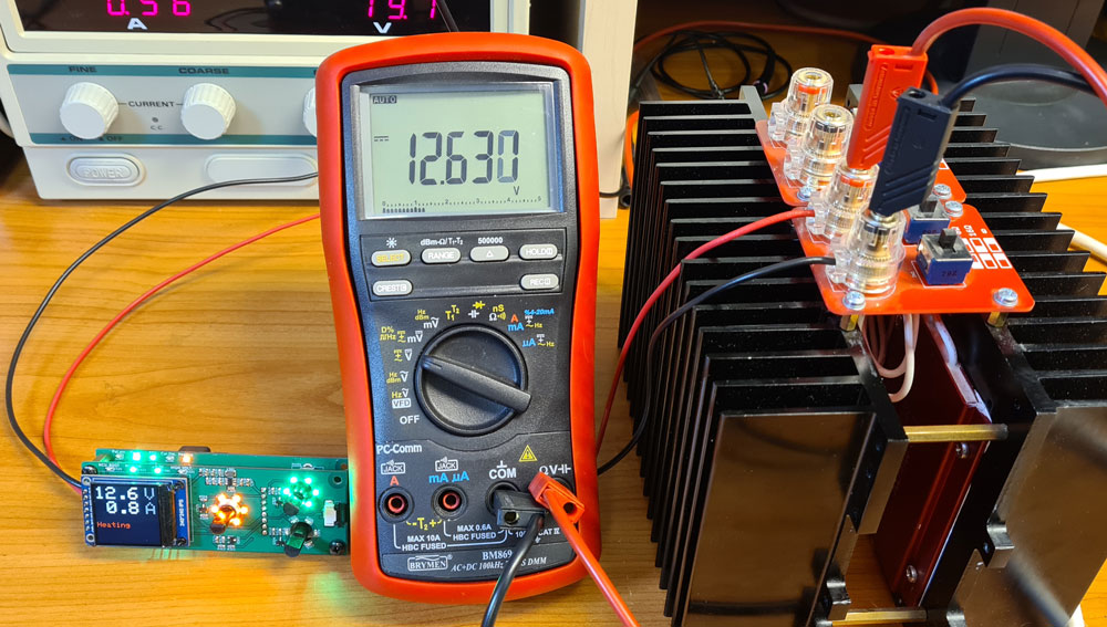
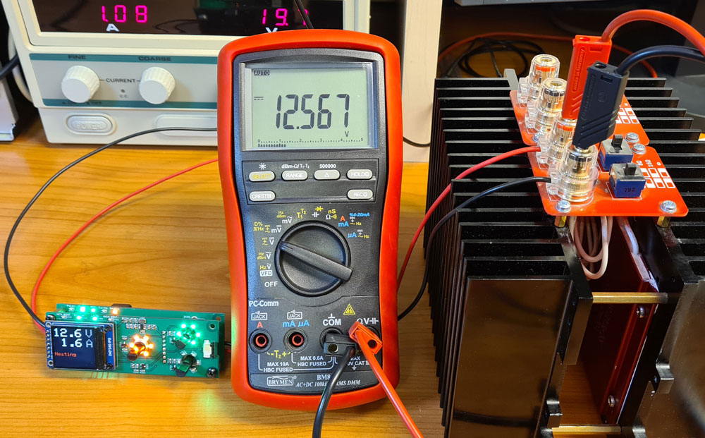
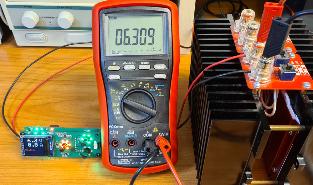
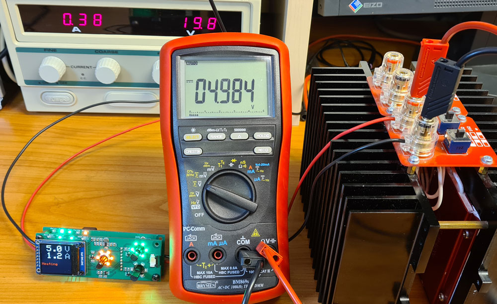
As when testing the µTracer’s internal PWM heater supply, a dummy load with 4, 8 and 16Ω resistance is used. Voltage and current measurements are performed by a multimeter.
Output voltage accuracy:


Conclusion: This heater supply provides significant accuracy improvement over the PWM solution, especially at low voltages. There is some voltage decrease as the XL4005 heats up, probably due to temperature coefficient the internal 0.8V voltage reference. This is after all a cheap buck converter, and it would probably possible to improve the temperature stability by using a more advanced buck converter chip.
Wire loss can be reduced by using thicker wire, and keeping the wires as short as possible. To fully compensate for the wire loss, I would have to extend the buck converter’s voltage feedback loop all the way to the tube sockets. This, however, would mean adding a voltage feedback line from each tube pin number, and the patch panel (described in next post) would need 2-pole connectors instead of 1-pole.
Current limiter
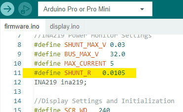
When designing current limiter for the heater PSU, I calculated resistor values to give a max selectable current limit of 2.5A. One concern was whether the current limiter would be stable, i.e. not start to oscillate. It’s time to find out whether it works as planned.
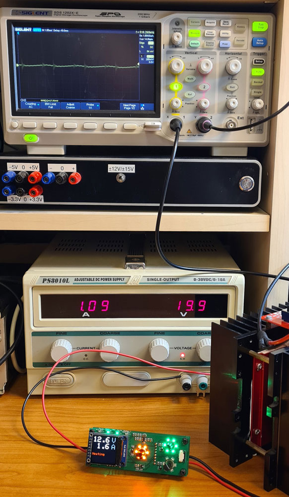
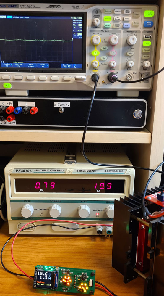
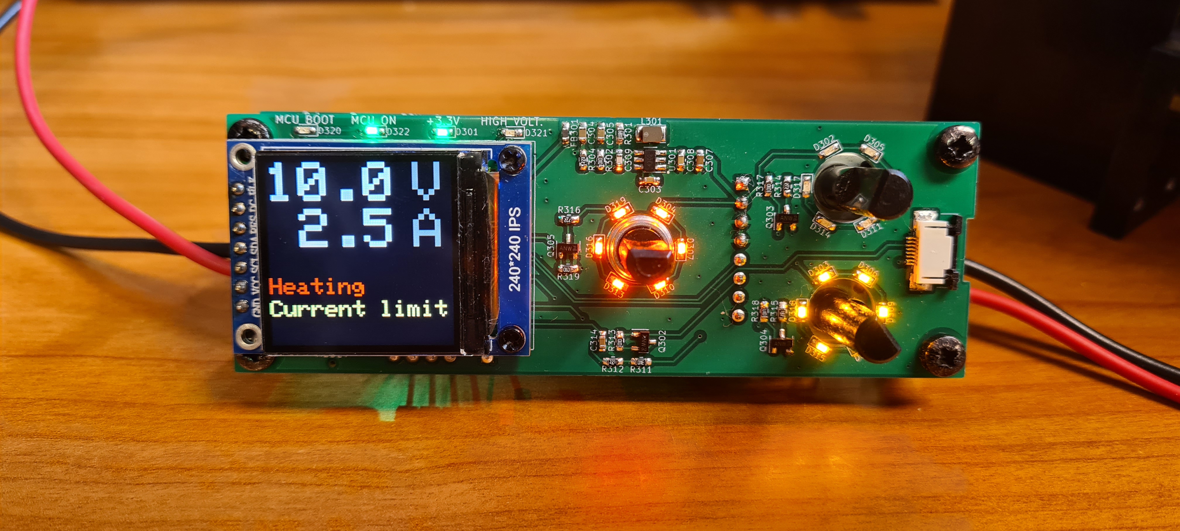
From the pictures above, we can see that green LEDs around the voltage potentiometer are lit when set voltage is the limiting factor (current limiter is inactive). When the current limiter is active, yellow LEDs around the current potentiometer are lit. Orange LEDs around the selector switch are lit when the heater output is turned on.
Next post is about putting the pieces together in an enclosure.

Leave a comment