
An easy way of implementing a regulated heater voltage supply, is to use one of the ubiquitous buck converter boards which are based on XL4015, and that come with adjustable voltage and current limit (up to 5A).
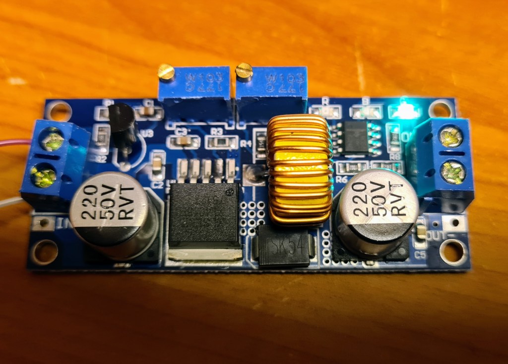
By desoldering the trimmer pots, and replacing them with panel mount potentiometers connected through wires, one could make the voltage and current settings easily accessible. One step further would be to add a rotary switch and some fixed resistor voltage dividers to allow quick selection of the most common heater voltages like 6.3V, 12.6V, etc. These resistor networks would most likely be placed on a PCB or prototype board, and then you’ve already taken one step towards building a custom PSU.
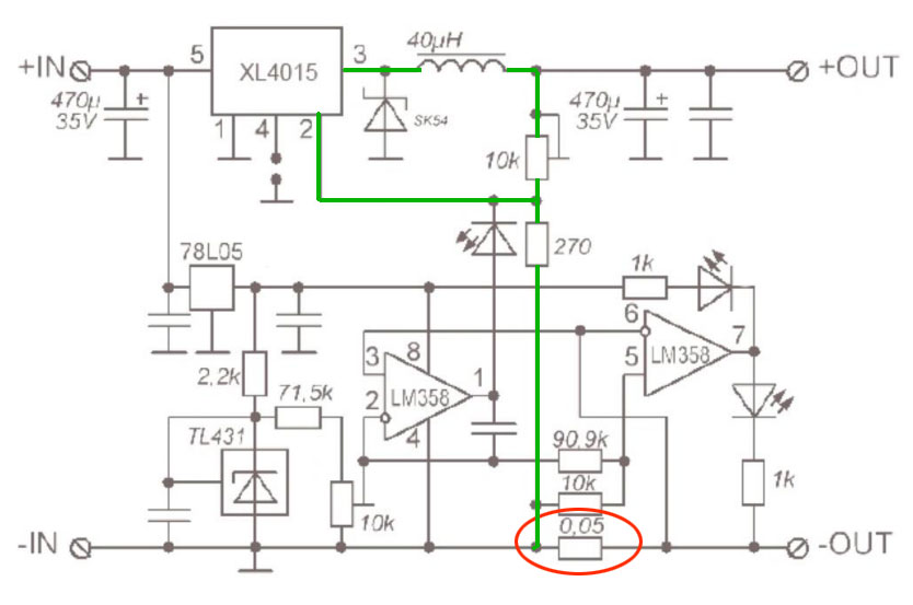
When looking a the schematic for these buck converters, I observe one significant drawback: The current limit functionality is based on low-side current sensing, using a 50mΩ resistor (marked with red), between the negative output terminal and GND. At e.g. 2.5A load, this causes a voltage drop of 50mΩ*2.5A=125mV, which the XL4015 cannot compensate for. In addition, you cannot connect the negative input- and output terminals to a common GND, because that would short the shunt resistor, and hence disable the adjustable current limiter.
For measuring output voltage and current, one would typically use a combined voltage- and amperemeter. This, however, has it’s own shunt resistor, which also will be connected in series with the load, causing more voltage drop.

Apart from the uncompensated voltage drop over shunt resistor(s), this buck regulator circuit doesn’t look to bad. The voltage regulation loop (drawn in green) consists of an adjustable voltage divider (10kΩ pot and 270Ω resistor), which feeds a selected portion of the output voltage, back to the feedback pin (2) of XL4015, where it is compared to the internal 1.25V voltage reference. If the feedback deviates from 1.25V, the XL4015 compensates for this by increasing or decreasing the output voltage.
The current limiter works by comparing the voltage over the 50mΩ shunt resistor, with an adjustable reference voltage created by TL431 and a voltage divider (the 71.5kΩ resistor and the 10kΩ pot). If the comparator (LM358 part in the middle of the schematic) senses that the shunt voltage higher than the reference voltage, it pulls it’s output towards +5V. This voltage is fed to the XL4015 feedback input through an LED (which both prevents reverse current flow when current limiter is inactive, and lights up when current limiter is active). The elevated voltage on XL4015 pin 2 fools the regulator to believe that the output voltage is higher than selected, and hence reduces the output voltage, which in turn reduces the current draw. In this way, a variable current limiter is achieved with a buck regulator which doesn’t have such functionality built in.
I decided to use this schematic as a basis when designing a custom heater PSU, which is described in my next post.

Leave a comment