
One prerequisite for a vacuum tube tester to deliver reliable measurements, is to supply the tube heaters with the correct voltage. Since filament breakage is a common failure on tubes, it will also be convenient to measure whether the filament draws the expected current from this voltage source.
µTracer comes with a built-in heater supply, based on PWM regulation; it takes the 19.5V from the DC adapter and chops it up to square pulses with variable pulse width, to produce an average filament power as close as possible to what a stable voltage and continuous current would generate.
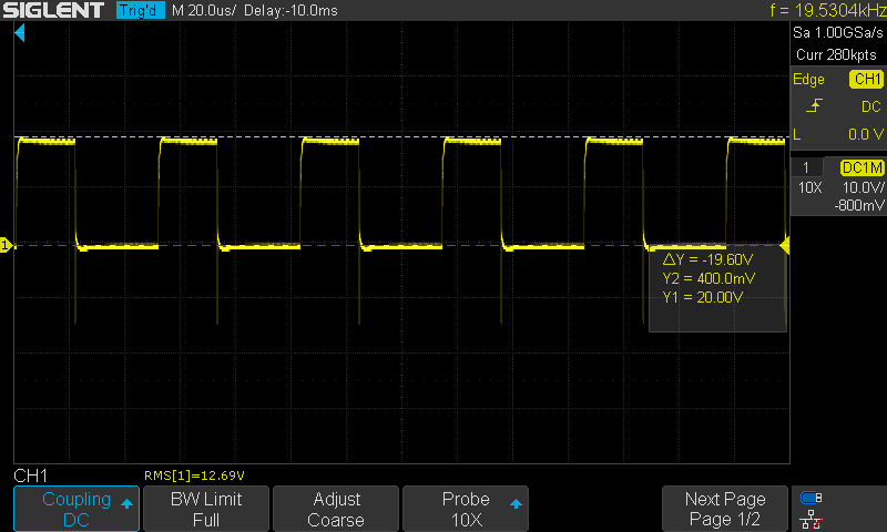
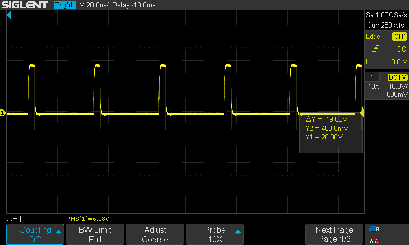
Here’s an example of what the heater terminals of the µTracer board delivers when heater voltage=12.6V is selected in the software. We can see that the 19.5V input is turned on and off at certain intervals to produce an output pretty close to 12.6Vrms. The pulse factor, i.e. the time the pulse is high, divided by the time of one periode, regulates the output power.
How does it work? I’ve drawn some colored lines on the µTracer schematic to highlight the relevant parts.
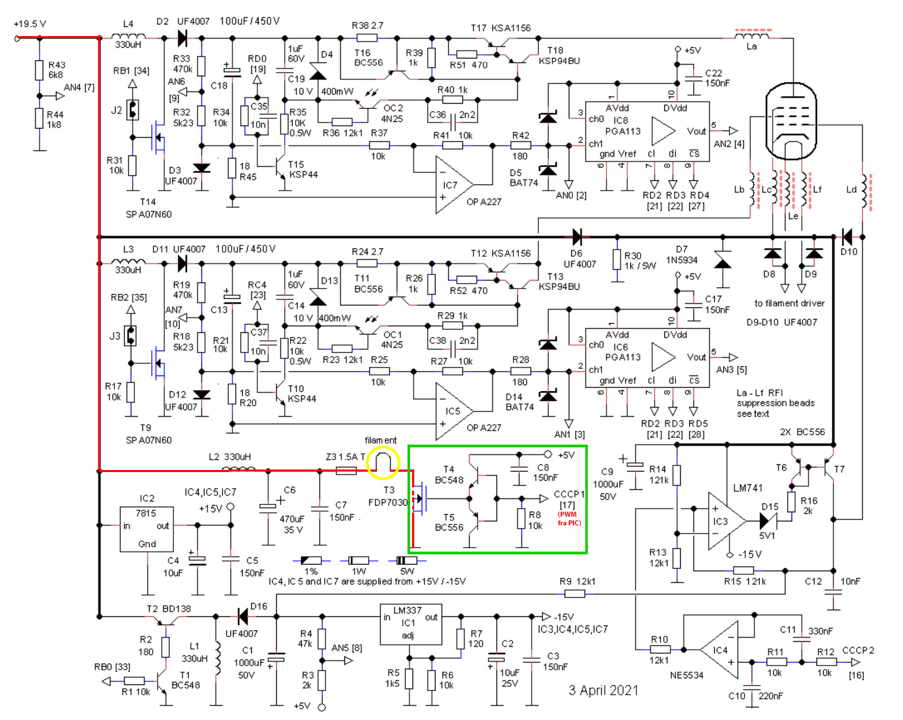
The red line shows the current path from the 19.5VDC input, via a filter choke and a fuse, through the tube filament, and between drain and source on a MOSFET which works as fast switch, turning the current on and off approx. 20.000 times a second. To ensure that the switching between on and off is quick and precise, the MOSFET gate is driven by a so called totem pole circuit (circuitry inside the green frame), which in essence is two bipolar transistors that conduct alternately to quickly charge and discharge the MOSFETs parasitic capacitance, and hence turning the MOSFET either fully on or fully off, and not somewhere in between. The two bipolar transistors are in turn controlled by a PWM pin on the PIC (not shown in this page of the schematic). The microcontroller generates a PWM signal with the appropriate pulse factor for the user selected voltage.
The PWM pulses may generate a lot of noise in the test circuit, and you might expect this to affect the measurements. This however is handled by the µTracer PIC. Right before each measurement pulse, the PWM is turned off.
How does the heater supply perform in practice? Lets put it to the test.

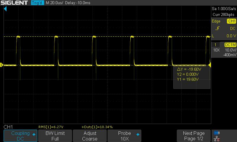
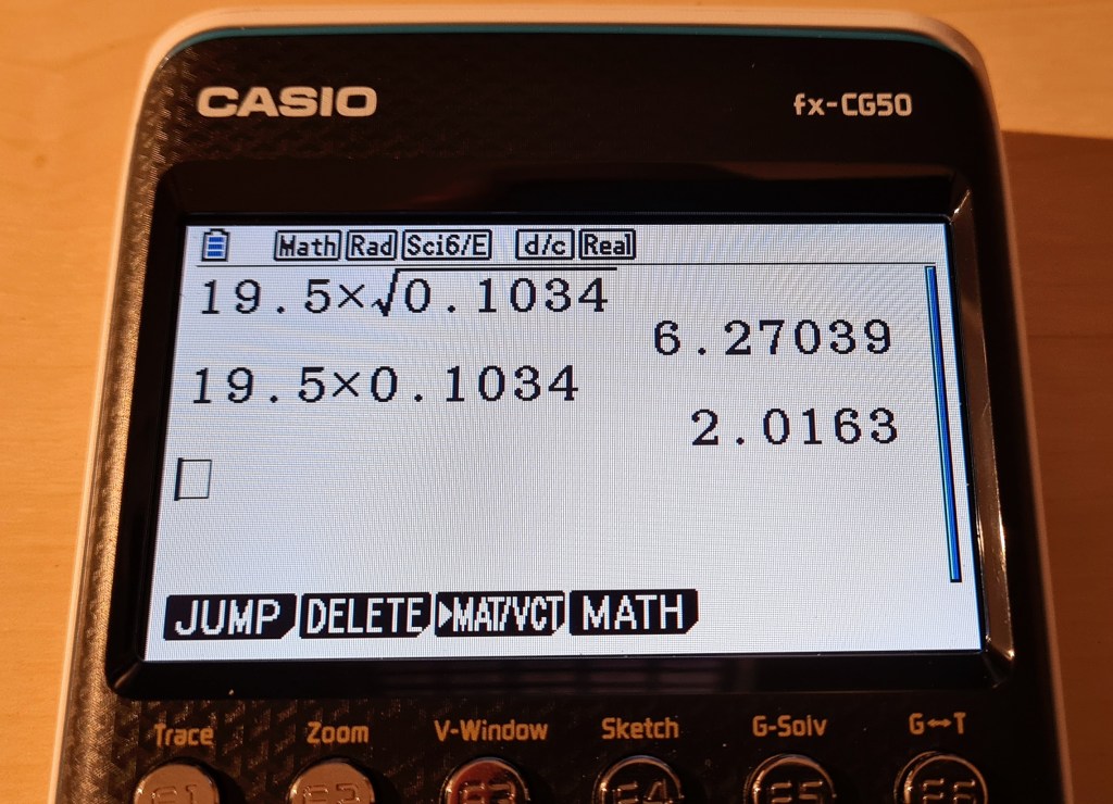
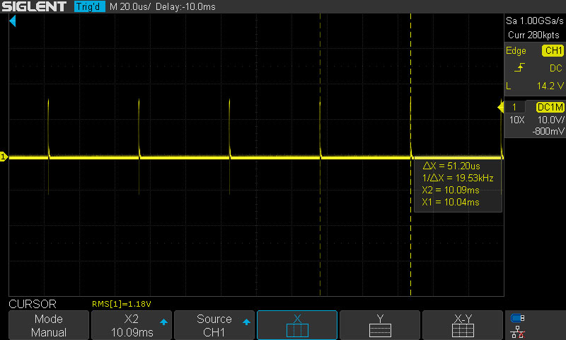
The RMS voltage of the PWM output, is the input voltage (in this case 19.5V) multiplied by the square root of the pulse factor (which the scope measured to be 10.34%). As we can see, the scope and the calculator agree that this gives 6.27Vrms.
The average voltage of a PWM is the input voltage (19.5V) multiplied by the pulse factor (10.34%). The calculated 2V average is what we would most likely see if measuring with a traditional voltmeter without True RMS capability. This may have confused some µTracer users.
With 6.3V still selected, it’s time to try with a heavier load. At 4Ω we are loading the circuit with something similar to the filament on an EL34, and this is probably pushing the µTracer to its limit, since recommended fuse for the heater circuit is T1.5A. However, I do expect any tube tester to be able to heat a common output tube like this.
- Voltage loss in wires between source and load.
- Increased loss in tracks and components on the PCB.
- Lower input voltage due to loss in power supply wires + a slightly less than perfect load regulation on the power supply. The µTracer measures the input voltage, but I don’t know if the PIC is programmed to compensate for voltage deviations during run-time.
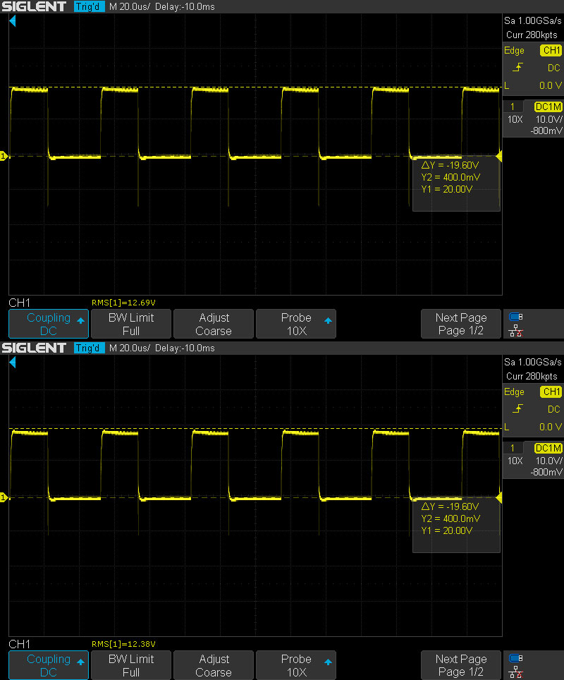
With selected heater voltage of 12.6V, and 16Ω and 8Ω load respectively, the µTracer performs reasonably well.
At lower voltages, in this case a selected heater voltage of 1.5V, the measured discrepancy is very high. At such low pulse factors, both the oscilloscope and the µTracer PIC may have accuracy limitations. With very low pulse factors, the on/off transients must be timed very precisely.
In the µTracer manual, the users are encouraged to use an external DC supply for very low heater voltages.
Conclusion: The built-in PWM heater supply can get you up and running with tube tests. For improved heater voltage accuracy, and making it easier to measure heater voltages- and currents, a continuous DC supply is preferred. One alternative is to use a buck converter, which will be described in my next post.

Leave a comment