Restoring, remodeling and creating electronic devices
Project: My first tube amplifier, part 2: construction
With the PCB manufactured, it was time to build the amplifier.
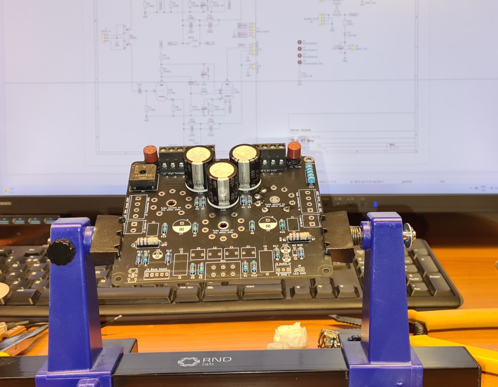
Soldering the components. Almost all parts were available from large component suppliers like Mouser, Digikey and RS, except the noval tube sockets, which I found here: https://www.ebay.com/itm/223494208015
Finished PCB, ready to be attached to the chassis bottom via four M3 brass standoffs. Just some more measuring and planning before starting to drill/cut holes.
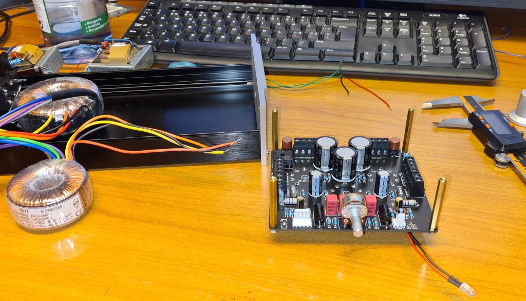
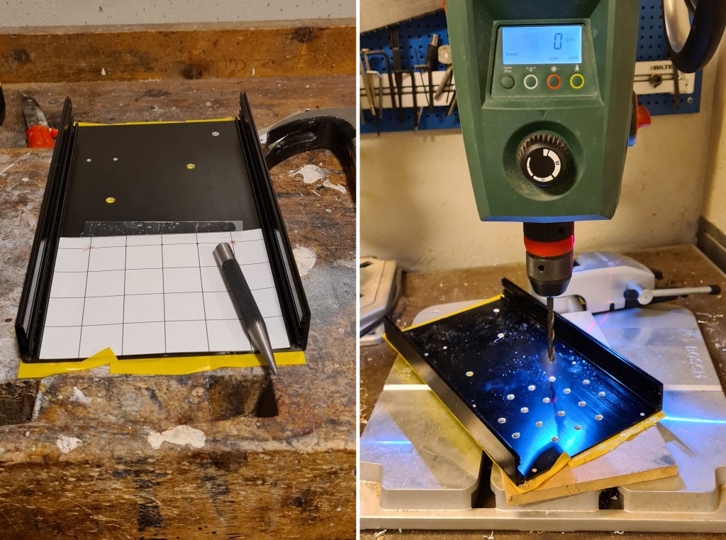
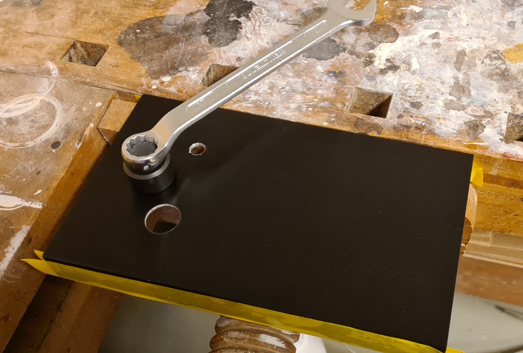
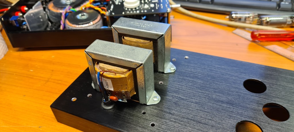
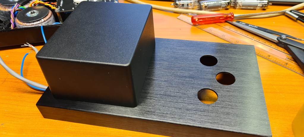
Drilling ventilation- and mounting holes on the chassis bottom part.Using a hole punch to create holes for tube sockets, in the chassis top part.Mounting output transformers to chassis.The OT’s are enclosed in an aluminium project box.Mounting of mains transformers, PCB and connectors. On the rear panel (to the left on the picture), there are audio input (3.5mm jack), speaker outputs (4mm banana jacks), mains inlet and bass boost switch. AC inlet and power switch were supplied with the chassis.


Leave a comment