
Some years ago, I restored a couple of Tandberg Huldra 7 broadcast receivers with stereo amplifiers based on EL84 output pentodes in single-ended configuration. The smooth and jazzy sound of these inspired me to build a small tube amp based on these radios audio stages.
From a third Huldra 7, which was beyond repair, i kept the transformers and other usable parts. The mains transformer was used for a power supply and test instrument, while the output transformers will be used in this amp.
Without any datasheet for the OT, I had to start with some measurements, using a function generator and an oscilloscope.

When feeding the input winding with 1V, the output winding delivered 26mV, and from this the transformer turns ratio can be calculated as 1/0.026 ≈ 38.5:1. The impedance radio is the square of the turns ratio: (38.5:1)² ≈ 1482:1.
For an EL84 tube working single ended, a load impedance around 5kΩ is allegedly optimal, so I expect the amp to perform best with a speaker impedance of around 5kΩ/1482 ≈ 3.4Ω. This may seem like an odd number, but the internal speakers of Huldra 7 had a nominal impedance of 3Ω, and separate Tandberg speakers from the same period were manufactured with impedances of either 3.2Ω or 4Ω, hence the amp’s output impedance may be a good compromise.
To allow the amp to be build in a small chassis, I used toroidal mains transformers, which are physically smaller, produces less heat and emits less EMI than traditional transformers. For this project, I used two transformers:
15VA, Pri: 2x115V, Sec: 2x6V, for heating (https://no.rs-online.com/web/p/toroidal-transformers/6719053)
50VA, Pri: 2x115V, Sec: 2x115V, for anode/screengrid supply (https://www.digikey.no/no/products/detail/triad-magnetics/VPT230-220/2090069)
The schematic for Huldra 7 was used as a starting point for the circuit design:
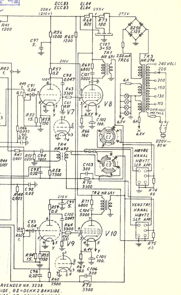
At first sight, the schematic may appear a little confusing, since there is an extra audio transformer + circuitry that makes the radio operable as an intercom when connected to a separate loudspeaker (typically placed in an other room of the house). There is also a tone control in there, with selectable RC-filters that affects the bass, midrange and treble, and different combinations of these filters are selectable through a rotary switch.
Two separate ECC83 (12AX7) are used as preamp stages, although this tube consists of two triodes, leaving two unused triodes. I guess the reason for this was to maximize channel separation.
My design is simpler, removing the unnecessary intercom functionality, and removing most of the tone control, except leaving the bass boost functionality in the feedback loop (selectable by SW1).

All tubes are cathode biased (self-biased). Global negative feedback is taken from the output transformers’ secondary windings (i.e. the speaker output), and inserted at the cathodes of the input tubes.
The heater transformer’s 6V secondaries are connected in parallell. 6V is the nominal output at full load, i.e. 2.5A. An zero load, the output is approx. 7V. The three tubes in my design will draw a total of 0.8A + 0.8A + 0.3A = 1.9A, with some luck the voltage will be close to 6.3V at this load.
The high voltage transformer’s 115V secondaries are connected in series, providing 230Vrms at full load (220mA). With no load, I measured a voltage of 255V. The DC output from the rectifier will therefore peak at about 360V when the tubes are cold and haven’t yet started drawing anode+screengrid current. Therefore, I’ve selected capacitors rated for 400V, and ensured proper spacing between pads and tracks on the PCB.
A chassis mount resistor (labeled J10 Ext.resistor in the schematic) drops the voltage to about 255V for the output stage, while R23 further drops the voltage to 220V for de preamp stage. These resistors also work as RC filters in cooperation with C15 and C16, to provide low-ripple DC for the two amplifier stages.
Breadboard prototyping the circuit, using Noval breadboard adapters:
PCB design in KiCad. All components are placed on one PCB, except the first drop resistor, which is chassis mount for better heat dissipation.

Production files (Gerber) and KiCad design files are published to Github: https://github.com/donpivo/TubeAmp_TA203
I uploaded the gerbers to jlcpcb.com for fabrication.
Next post describes the building process of this amp.

Leave a comment