
Sometimes I come up with practical solutions to specific problems, and end up with something more versatile than originally intended.
It started when I got a 50″ LED for free due to the slight inconvenience that it didn’t work. There was sound, but no picture. Basic troubleshooting led me to the idea that the most likely cause was one or more defective LED backlight strips, but I didn’t want to order new ones before the suspicion was confirmed. Each strip contained a lot of LEDs in series, and the LED terminals weren’t accessible for individual testing. This meant I needed a source of quite high DC voltages, which was also current limited to avoid destroying more LEDs. One can buy special test instruments this purpose, but I decided to make something.
From a trashed Huldra 7 radio that was beyond repair, i scavenged the mains transformer (among other things). With no load, the transformer delivered 260Vrms and it’s T250mA fuse on the secondary side gave an impression of what it could deliver (though I wouldn’t deliberately push it to that limit).
Rectifying and smoothing the output voltage is pretty straightforward, but I needed to find a way to regulate the voltage and limit the current. For low voltages, one can simply build a circuit around a voltage regulator like LM317 (or lots of other alternatives), but for high voltages, there are few options. The only one i found was the LR8, which is adjustable up to 438V, but with it’s max output current of 20mA and max power dissipation of less than 1W (in TO-92 package), would have been to weak.
After googling “high voltage regulators” for inspiration, I came up with this concept:
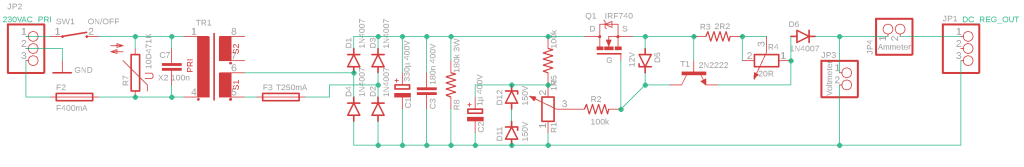
The central component here is the IRF740 N-channel power MOSFET. Unregulated DC voltage is passed in to D, and the output voltage from S will follow the voltage reference at G. A voltage divider consisting of a 100kΩ resistor and two 150V zener diodes in series, delivers a reasonably constant 300V, and a potentiometer adjusts what fraction of the 300V which is to be delivered into MOSFET gate. The 12V zener protects the MOSFET from too high Vgs voltage.
The bipolar transistor works as a current limiter: as the output current increases, the voltage over resistors R3 and R4 increase proportionally until the bipolar transistors’ Vbe reaches a threshold of about 0.6V, where it starts to conduct current from C to E. This current drags the MOSFET’s gate voltage down. This in turn causes the MOSFET to reduce the voltage at S, and the lowered voltage leads to a lowered current draw.
The circuit would have been enough to test LED strips, but since I now was on my way to create a variable PSU, I decided to extend the circuit to make it suitable for working as both a capacitor leakage tester, and a power source for prototyping small vacuum tube circuits.
Using the two 150V zeners as voltage reference means the max output voltage is approximately 300V, while the transformer can deliver around 250Vrms at low current draw, making about 350V rectified DC. If I had increased the total zener voltage to 350V, it would cause a problem when the circuit is loaded with more current, and the rectifier output voltage drops below that: the voltage regulator would no longer be stabilized.
I needed to find a more flexible voltage reference, and actually I already had found it: the LR8 linear regulator. Feeding the MOSFET gate from the LR8 voltage output would do the trick.

To make the circuit work as a capacitor leakage tester, a µA-meter was necessary, and the same ammeter would also have to handle larger currents when the circuit was used as a generic PSU or for testing LED strips. This meant using multiple shunt resistors for different current ranges. Also, different current limits would be needed for different purposes.
I came up with the idea of giving the PSU four modes, selectable by push buttons:
1. Generic PSU
2. LED TV backlight test
3. Capacitor leakage test
4. Capacitor discharge
These modes would require different current limits and ammeter ranges, and i decided to use relays for connecting the correct shunt resistors, and a microcontroller to control the relays. An ATMEGA328P, known from basic Arduino boards, was chosen for the purpose, and the circuit had grown to this:
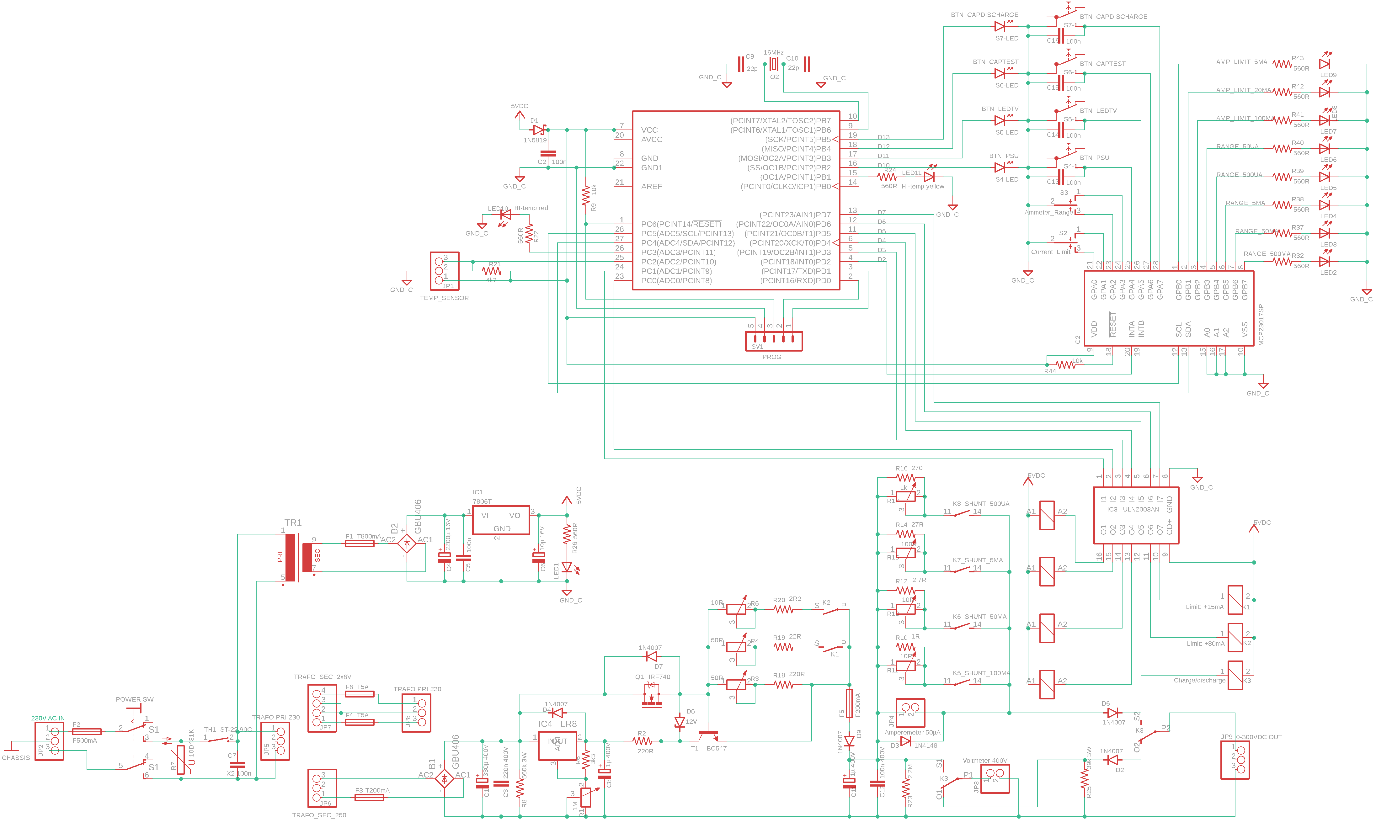
When using a MOSFET as linear voltage regulator, it will dissipate lots of heat, and will have to be mounted on a heatsink. The temperature should also be monitored to prevent overheating. I used a DS18B20, mounted on the back of the MOSFET.
LED indicators show all the different combinations of modes, current limits, ammeter current ranges, and temperature status. Without enough IO ports on the ATMEGA, I used an MCP23017 IO extender, which has 16 IO ports, programmable via I2C. A ULN2003 with 7 darlington pairs is used to drive the relays.
The four modes are programmed to work like this:
1. Generic PSU: The current limit is set to 100mA, with the option of reducing the limit to 20mA or 5mA. For these three current limits, the ammeter range is automatically set to 100mA, 50mA or 5mA.
2. LED TV backlight test: The current limit is set to 20mA and ammeter range is 50mA.
3. Capacitor leakage test: The current limit is 5mA, and the ammeter range is initially set to 5mA, with the option of selecting ranges of 500µA or 50µA.
4. Capacitor discharge: Output terminals are disconnected from the PSU, and instead a discharging resistor is connected. The voltmeter is also connected, allowing the user to monitor the discharge process.
It’s been a few years since i built this thing, and I hadn’t yet learnt to make proper PCBs, to the circuit was built on a prototype board:
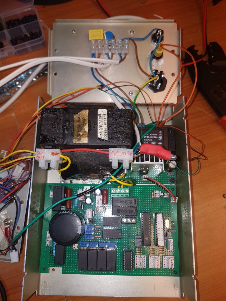
The small inside heatsink is just for the 5V regulator that drives the control circuit, while a large heatsink on the back of the cabinet (not seen in this picture) is used for the power MOSFET.
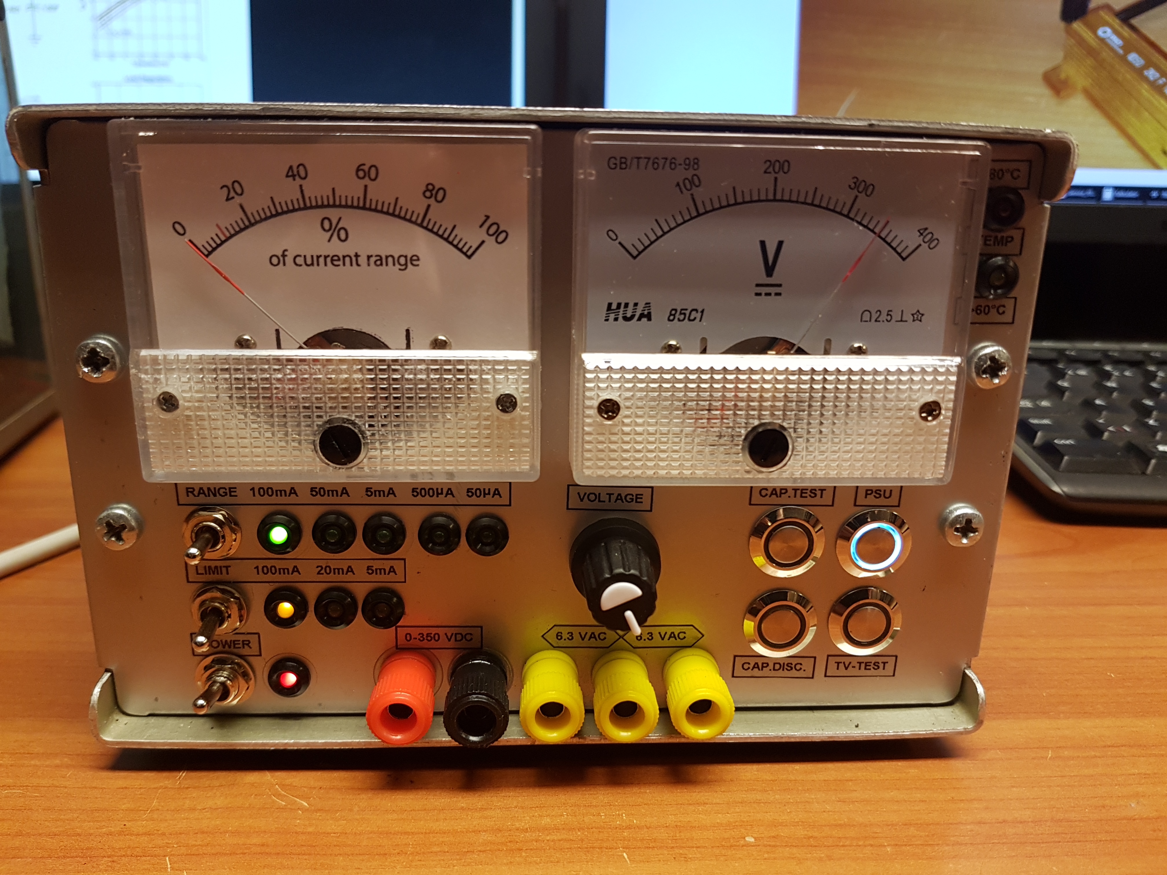
Finished build, in a quite compact box.
Usages:

Leave a comment