
In the beginning, there were some teak mouldings from an old living room table, mahogany bars from a trashed radio console cabinet, some pieces of MDF and plywood, a tuning capacitor, a spool of enameled copper wire, and no prior knowledge of loop antennas; that is a good start 😄
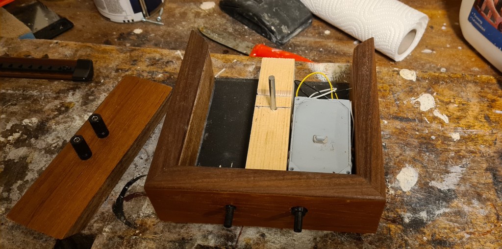
I built a base of MDF and teak, inserted the tuning capacitor a rotary switch, and a couple of screw terminals.
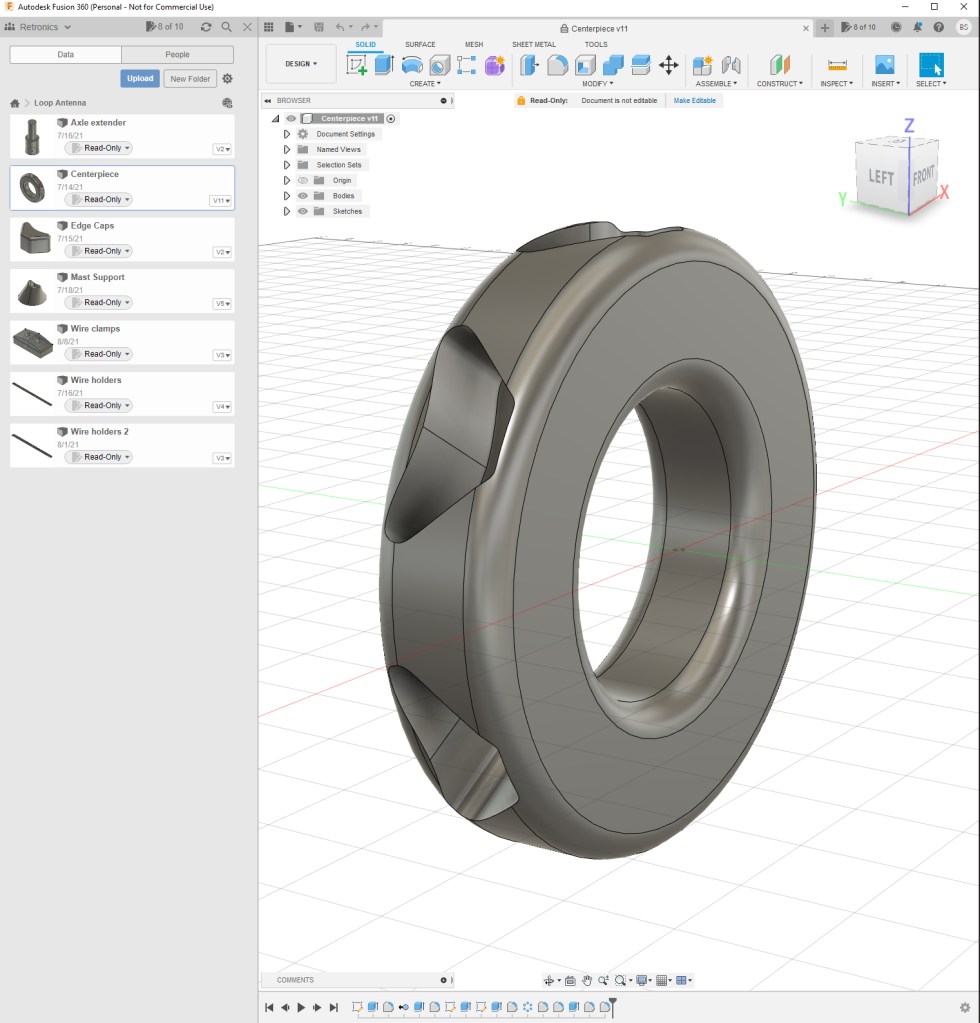
Fusion 360 was used for modeling the plastic parts. This is a professional design software which is available in a free version for personal use. The “donut” will form a centerpiece for the antenna arms.
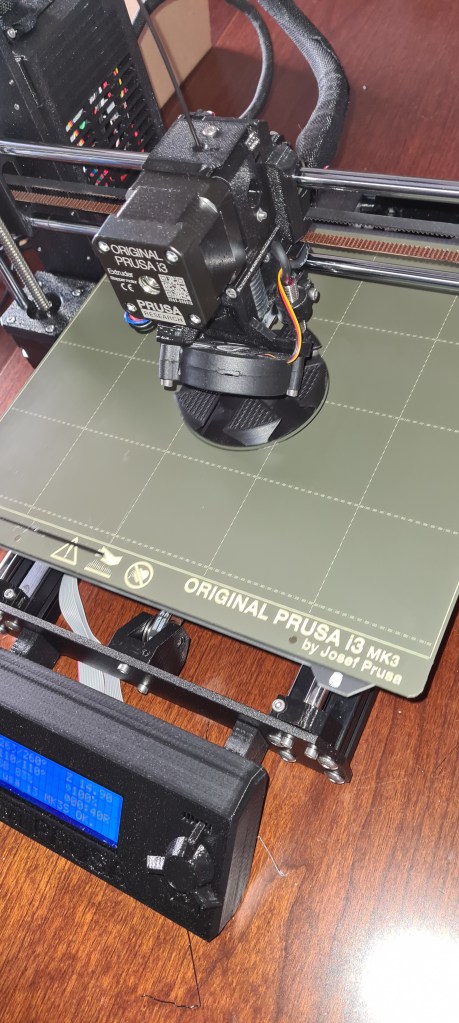
3D printing, using a Prusa i3 MK3S+. The plastic material used for this project is ASA, an improved version of ABS.
Surface treatment: Though the print quality is good, one could easily see that the parts are 3D printed, with a slightly uneven surface, but this can be made smoother. I used fine sanding paper, followed by a chemical process involving acetone vapor. Liquid acetone will quickly dissolve ABS or ASA, while the right amount of acetone vapor will only liquify the object surface, causing it to smooth out itself.
This can be done in a quite rudimentary process: Put the object in a plastic storage box, together with some paper towels soaked in acetone. Let it stay there for the right amount of time, take the object out and let it harden. A fan inside the box speeds up the process, which in this case took about 15 minutes.

The tuning capacitor I used has two sections, each variable from 13 to 560pF. With a switch, I can decide to use either one section, or both sections in parallell, extending the range up to approx. 1.1nF.

In each antenna arm, I mounted 3D-printed hooks, on which the coil wire can be wound.
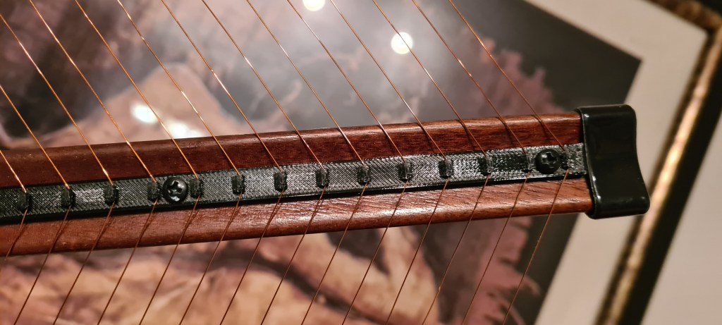
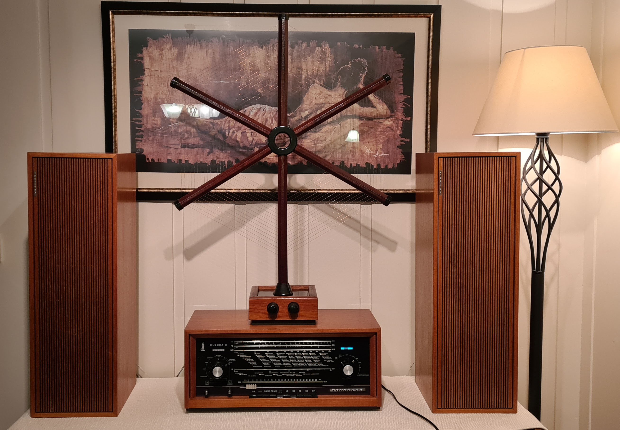
The antenna diameter is 65 cm, and has two separate windings. The two outer turns form a pickup-coil which are to be connected to the radio receiver. Inside of these are 15 turns forming the antenna, which has an inductance of about 120µH. In parallell with a capacitor of either 13-560pF or 26pF-1.1nF, the frequency ranges can be calculated to 614 kHz-4MHz or 438 kHz-2,8 MHz, depending on the switch setting.

The pieces are mounted together, and the base is closed by a lid made of plywood, coated with black paint and polished to a blank surface.


Leave a comment